
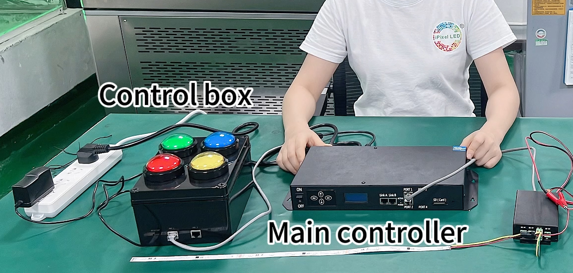
A: No. We design the project-specific control interface and integrate selected commercial controllers when they provide the required platform. In this case, the four-key control board, PCB, finished control box, lighting programs and LED integration were developed by iPixel, while the master and terminal controllers were third-party devices.
Custom LED Control Board & System Integration - From Operator Input to Programmed Lighting
Engineering methods for turning a customer's operating requirement into a finished LED control solution, including custom control-board development, physical operator interfaces, offline program creation, third-party controller integration and addressable LED system validation.
WHERE_IT_APPLIES
· Equipment manufacturers that need a simple physical interface for selecting predefined LED programs
· Illuminated barriers, guardrails, guidance lines and visual status indicators
· Arcade machines, amusement equipment, vending systems, display fixtures, refrigeration equipment and smart furniture
· Applications using addressable LED strips, LED neon, rigid LED bars or custom LED boards
· Projects that require button, sensor, PLC or host-equipment signals to trigger specific lighting behavior
· Visual indication and operating-status communication; not a certified emergency-stop or functional-safety system unless separately specified and validated
CAPABILITY_SNAPSHOT
· Goal: convert complex LED program selection into a simple, repeatable operator action.
· Core risks: unsuitable user interface, incorrect program selection, communication mismatch, unstable field wiring, visible light dots and inconsistent program behavior.
· Deliverables: custom control PCB, finished operator box, button-to-program logic, RS485 interface, SD-card lighting programs, SPI2811 LED integration, wiring definition and system validation.
· Project approach: develop the custom parts in-house and integrate selected commercial modules where they are technically appropriate.
INPUTS_WE_NEED
· Required operator actions and the meaning of each button, sensor or external input
· Whether a selected program is momentary, latched, timed, interrupted or reset by another command
· Required colors, scanning direction, animation speed, brightness and transition behavior
· LED type, control protocol, pixel quantity, segment quantity and maximum run length
· Power architecture: input voltage, power-supply location, current budget and grounding method
· Controller-to-first-LED distance, RS485 cable distance and cable-routing restrictions
· Mechanical drawings, enclosure space, connector direction and installation environment
· Optical structure: direct-view LED, diffuser, silicone tube, light guide or 360-degree luminous profile
· Required documents: wiring diagram, interface definition, program list, installation guide, test record and labeling
· Target market, compliance requirements, annual volume and sample-validation plan
PROBLEMS_WE_SOLVE
· The commercial LED controller is technically capable but too complicated for front-line operators.
· Employees should not need a computer, lighting software or controller menu for routine operation.
· A physical button, sensor or machine signal must trigger a specific stored lighting program.
· The customer's equipment uses a different control voltage or communication interface from the selected LED controller.
· LED products, controller programs, communication wiring and the mechanical lighting structure must be tested as one system.
· The final illuminated surface must look continuous even though the light source is an addressable LED strip.The project needs a repeatable finished control box rather than a loose development board.
KEY_ENGINEERING_CONTROLS
Custom operator-interface electronics
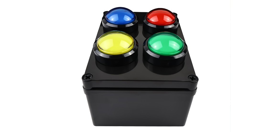
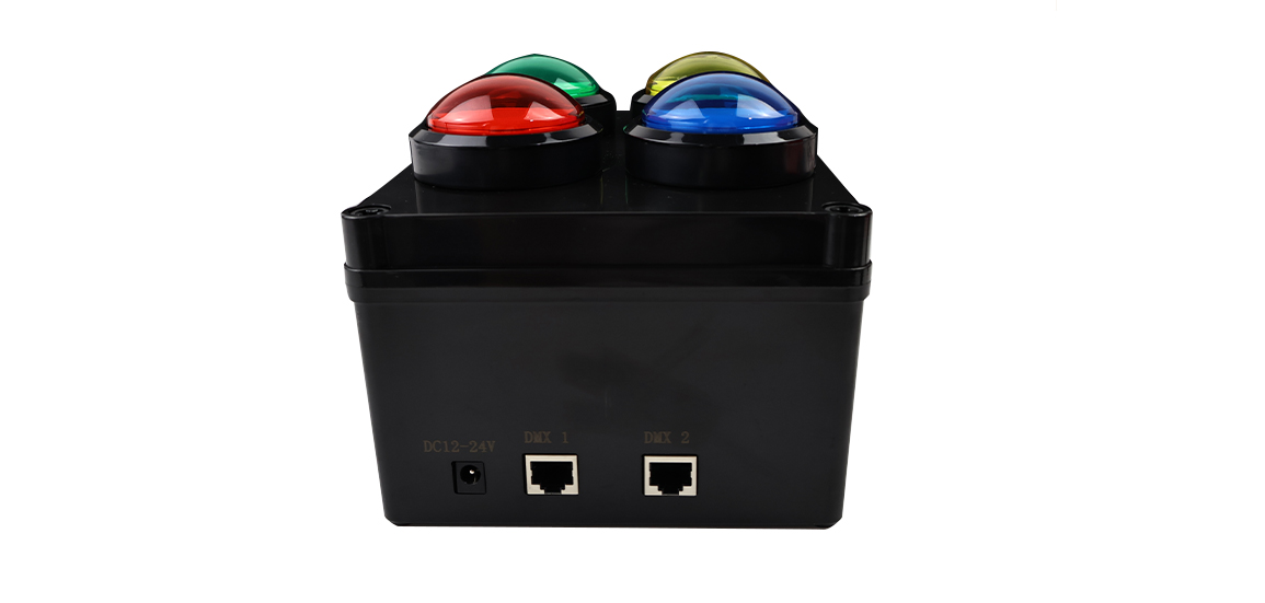
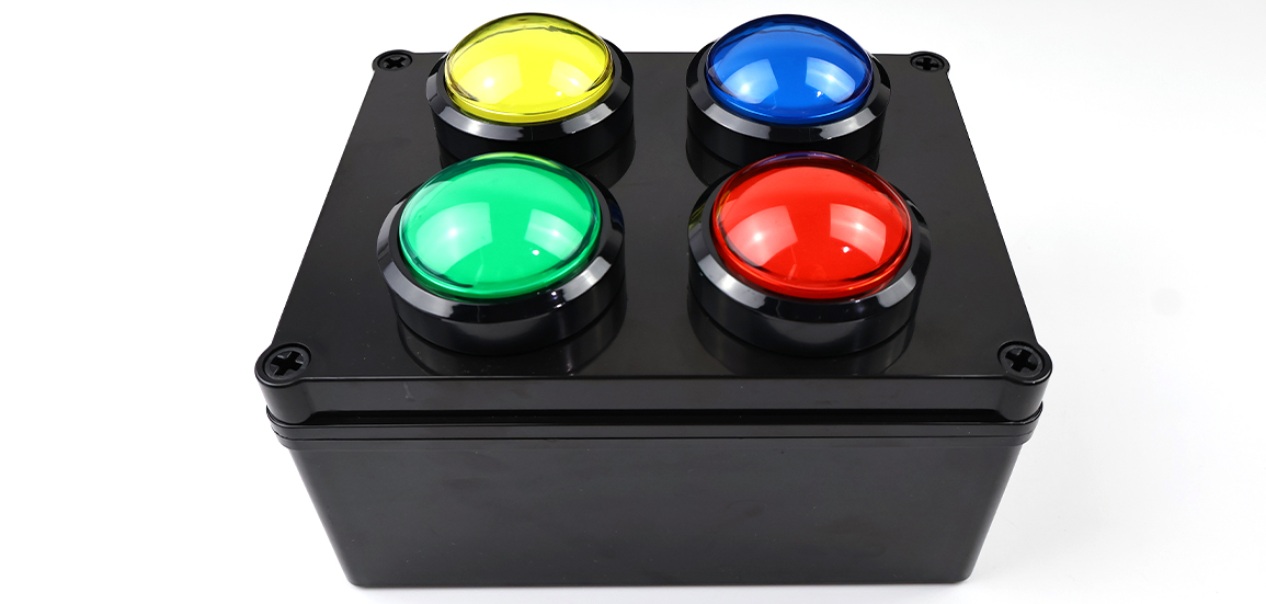
For this project, we designed a dedicated four-key control circuit rather than asking the operator to use the original controller interface. The custom board accepts a 24V DC field input and uses MCU-based logic to recognize the selected key and send the corresponding command through RS485.
Communication protection and signal integrity
The field interface incorporates transient/ESD protection and resettable overcurrent protection. RS485 grounding, cable routing and 120-ohm termination are defined according to the final communication topology. These details help reduce intermittent commands and communication errors in an equipment installation.
Offline program engineering
The lighting programs are prepared in advance and stored on the SD card used by the selected offline master controller. Program segments, playback speed, frame frequency and brightness can be configured during commissioning. Routine operation can then be completed without opening lighting software.
Button-to-program mapping
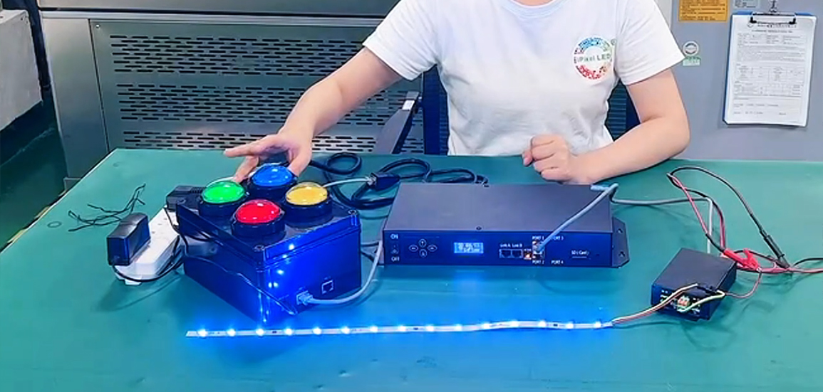
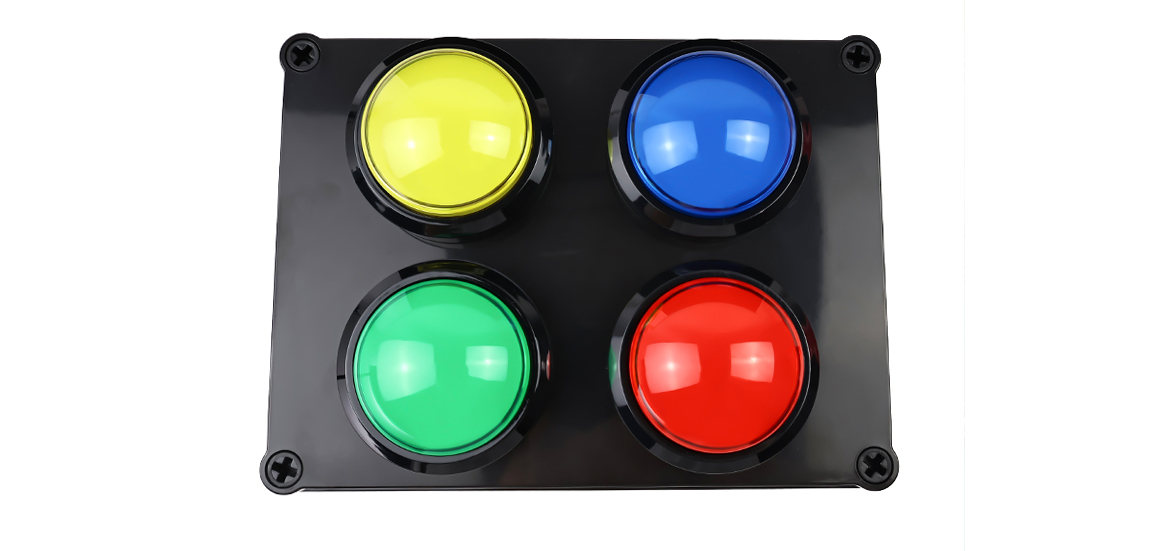
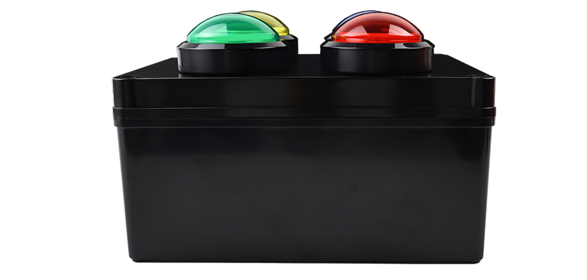
The red, yellow, green and blue buttons are mapped to four corresponding color-scanning programs. After a button is pressed and released, the selected program remains active until the operating state is changed. The same logic can be redesigned for other colors, effects, priorities, timers or machine states.
Distributed output and protocol matching
The selected terminal-control platform supports DMX512 and TTL output with configurable 1, 2 or 4-port modes. For this delivered application, the load side uses an SPI2811-type addressable LED signal. Controller capacity, port mode, cascade quantity and cable length must be confirmed for each project rather than assumed from a single module rating.
LED and optical-structure integration
The addressable flexible LED strip is installed inside a 360-degree light-diffusing tube, which is then integrated into the barrier. The diffuser changes a narrow LED source into a continuous luminous element that can be seen around the barrier. LED pitch, tube transmission, power density, bending radius and scanning speed must be evaluated together.
Transparent sourcing boundary
The offline master controller and terminal-control module in this case are selected third-party devices. Our engineering work covers the custom control-board design, PCB production, control-box assembly, lighting-program creation, LED product matching, controller configuration, wiring definition and complete system integration.
VALIDATION_TESTING
The validation plan is defined around the final operating logic and installation. Typical checks for this type of solution include:
| Validation item | Acceptance focus |
| Button recognition and latching | Each key consistently activates and maintains the correct program. |
| Red/yellow/green/blue mapping | Displayed color and stored program number match the approved function list. |
| RS485 communication | No missed or unintended commands under the agreed cable length and routing. |
| SD-card offline playback | Programs load correctly after startup and recover to the agreed state after a power cycle. |
| Scanning continuity | No unexpected pauses, color errors or visible data artifacts along the LED run. |
| Brightness and speed | Brightness, frame frequency and scanning speed match the approved visual sample. |
| 360-degree optical appearance | The installed tube provides the agreed visibility and acceptable dot/hotspot performance. |
| Power and temperature rise | Voltage drop, current and temperature rise remain within the agreed design limits. |
| Connector and wiring check | Pinout, polarity, grounding, strain relief and labels match the installation drawing. |
| Repeated operation | The system remains stable through repeated button selection and state changes. |
COMPLIANCE_DOCUMENTATION
· Custom board schematic and PCB production files retained as controlled internal engineering documents
· Control-box interface definition and connector pinout
· Button-to-program function list
· Controller and SD-card configuration record
· LED product specification and approved sample
· Wiring and installation diagram
· Project-specific validation checklist and result recordRevision control for board, program and wiring changes
PROVEN_IN_PROJECTS
In one repeatedly delivered project, the customer installed our addressable flexible LED strips inside a 360-degree light-diffusing tube integrated into an equipment barrier.
· Four large color-coded buttons provided an intuitive operator interface.
· Our custom control board converted the physical input into an RS485 command.
· Four red, yellow, green and blue scanning programs were prepared and stored on the commercial master controller's SD card.
· A selected color program remained active after the button was pressed and released.
· The distributed controller delivered the program to SPI2811-type addressable LED strips.
· The finished solution allowed employees to change the barrier's visual indication without using a computer or navigating controller menus.
· The project has been supplied repeatedly, demonstrating that the design can be reproduced as a finished assembly rather than remaining a one-off prototype.
RELATED_INDUSTRIES_PRODUCTS
Related industries
· Arcade and gaming equipment
· Refrigeration and display cabinets
· Wardrobes, kitchen cabinets and smart furniture
· Retail displays and illuminated shelving
· Vending machines, kiosks and automated retail equipment
· Coffee machines, charging equipment and industrial devices
· Amusement equipment and interactive installations
Related products and capabilities
· Addressable flexible LED strips
· LED neon and 360-degree luminous tubing
· Rigid LED bars and custom LED boards
· Custom control-board development
· Cable, connector and wiring-harness integration
· R&D and OEM/ODM support
· Testing, validation and change control
FAQ
A: Yes. Button quantity, color, priority and program behavior can be redesigned. A button can trigger a latched, momentary, timed, sequential or reset function according to the equipment workflow.
A: Yes. Lighting programs can be prepared in advance and stored in an offline controller. Routine operation can then be completed from physical buttons or equipment signals.
A: The final protocol depends on the selected LED and controller architecture. This delivered application used an SPI2811-type addressable LED signal, while the selected terminal platform also supports DMX512 and TTL output modes.
A: Yes, but the project is usually more reliable when the board, LED load, power, connectors, wiring, optical structure and operating program are evaluated together.
A: No. The delivered system provides visual indication. It is not a certified emergency-stop or functional-safety system.
A: Provide the required operator actions, input signals, LED type and quantity, color/effect list, power architecture, cable distances, mechanical drawings, installation environment and compliance target.