
For a rounded shelf edge, plan the neon's bending plane, corner radius, groove, end treatment and cable route together. A suitable continuous bend can avoid a separate joint at the corner. The appearance where two capped ends meet is a different issue.
This note uses supplied 8x8 neon installation information to help display-fixture engineers and product teams define the mechanical details before machining and sample assembly. The nominal profile size does not specify its allowed bending direction or minimum radius.
Separate the corner problem from the end-junction problem
The earlier arrangement considered for the shelf front could not bend in the required plane, so separate sections were needed at the left and right turns. Those junctions introduced gaps and interrupted the light line. The supplied engineering response was to select a construction that could follow a rounded path in the required plane.
This reduces the need for a splice at each suitable rounded turn. It does not remove the non-emitting space in the end treatment where a strip terminates or meets another strip.
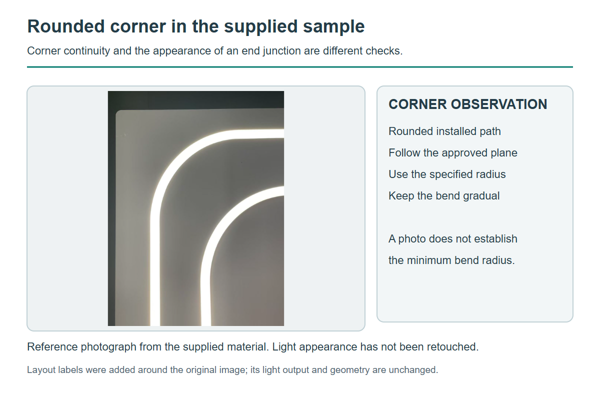
Supplied corner reference showing a rounded illuminated path. The engineering notes describe uniform corner illumination; the photograph does not establish a numerical radius or photometric tolerance. Select the figure to view the full-size image.
Confirm the bend relative to the emitting face
Identify the emitting face and show the intended curve on the installation drawing. Then confirm that the selected product supports that bending plane. Terms such as “side-bending” should be checked against the product's actual direction illustration, rather than used as the only selection instruction.
Emission direction and bending direction are separate descriptions. It would be incorrect to assume that every front-emitting product has the same bending limits, or that any 8x8 profile can follow a curve in every plane.
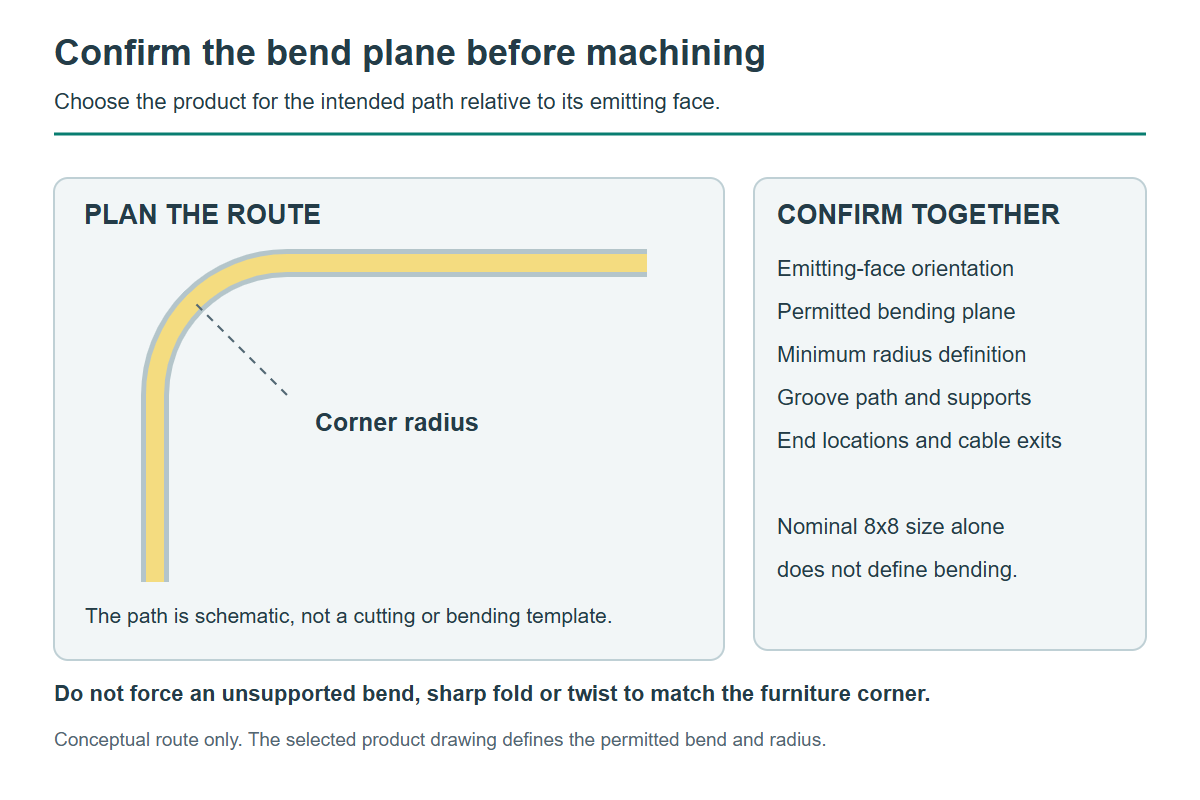
Conceptual route-planning illustration. The selected product must support the required bending plane relative to the emitting face; use its approved drawing for the minimum radius. Select the figure to view the full-size image.
Use the approved product drawing to define the minimum bend radius and where that radius is measured. The installed path should remain within the selected product's limits throughout the corner. The engineering feedback identifies an undersized corner radius as a risk to the internal circuit assembly.
Do not turn an illustrated rounded path into a sharp right-angle fold or force an unsupported bend or twist to fit the furniture. The supplied material does not establish a universal numerical radius for all products described as 8x8 neon.
Define the groove for the assembled profile
The supplied installation sketch labels both groove width and depth as 8 + 0.2mm for the illustrated 8mm configuration. Read that alongside the selected product dimensions and the panel drawing. It is an example reference, not a general groove specification for every nominal 8x8 product.
In this example the additional 0.2mm belongs to the illustrated overall dimension; it should not be doubled into an allowance on each side. Confirm the final width, depth, manufacturing tolerance and actual fit before releasing the panel for production.
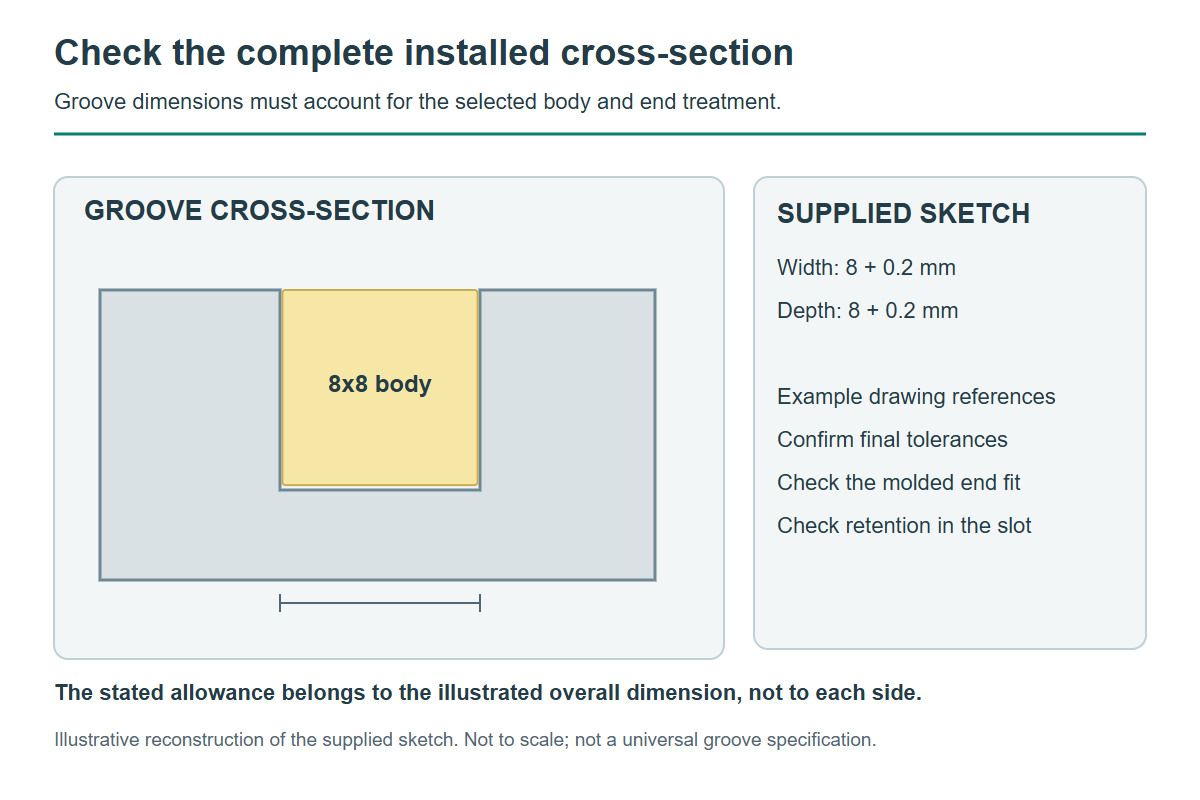
Illustrative reconstruction of the supplied groove sketch, which labels width and depth as 8 + 0.2mm. Confirm final dimensions, tolerances, end treatment and retention for the actual product and panel. Select the figure to view the full-size image.
A slot that is too tight can make installation difficult. Fit must also retain the light correctly after installation. Check the body, molded end, panel material, machining variation and the intended fixing method together rather than approving a groove from the body size alone.
The engineering notes describe molded end treatment matched to the strip width, which can simplify a consistent-width groove. The end still has an assembled length and a cable-exit envelope. Confirm those dimensions on the released part drawing; the reference photograph is not a dimensional inspection.
Choose the outlet direction before the panel is made
The supplied notes describe straight, side and bottom cable-exit options for different layouts. The change discussed here was from a straight outlet to a side outlet to support concealed routing. This describes an outlet choice; it does not mean every strip has a powered lead at both ends.
Outlet choices and the space to confirm
| Outlet option | What to show on the drawing |
|---|---|
| Straight exit | Space beyond the end for the cable, connection and intended bend. |
| Side exit | Which side, the orientation of the emitting face, and the path from the end to the panel opening. |
| Bottom exit | Opening position below the assembly and access to route and connect the lead. |
Specify each end independently: its position, cap or lead treatment, outlet direction and connection destination. Use an orientation view to remove ambiguity about “left,” “right” or “bottom.” Cable length and connector details belong with that definition.
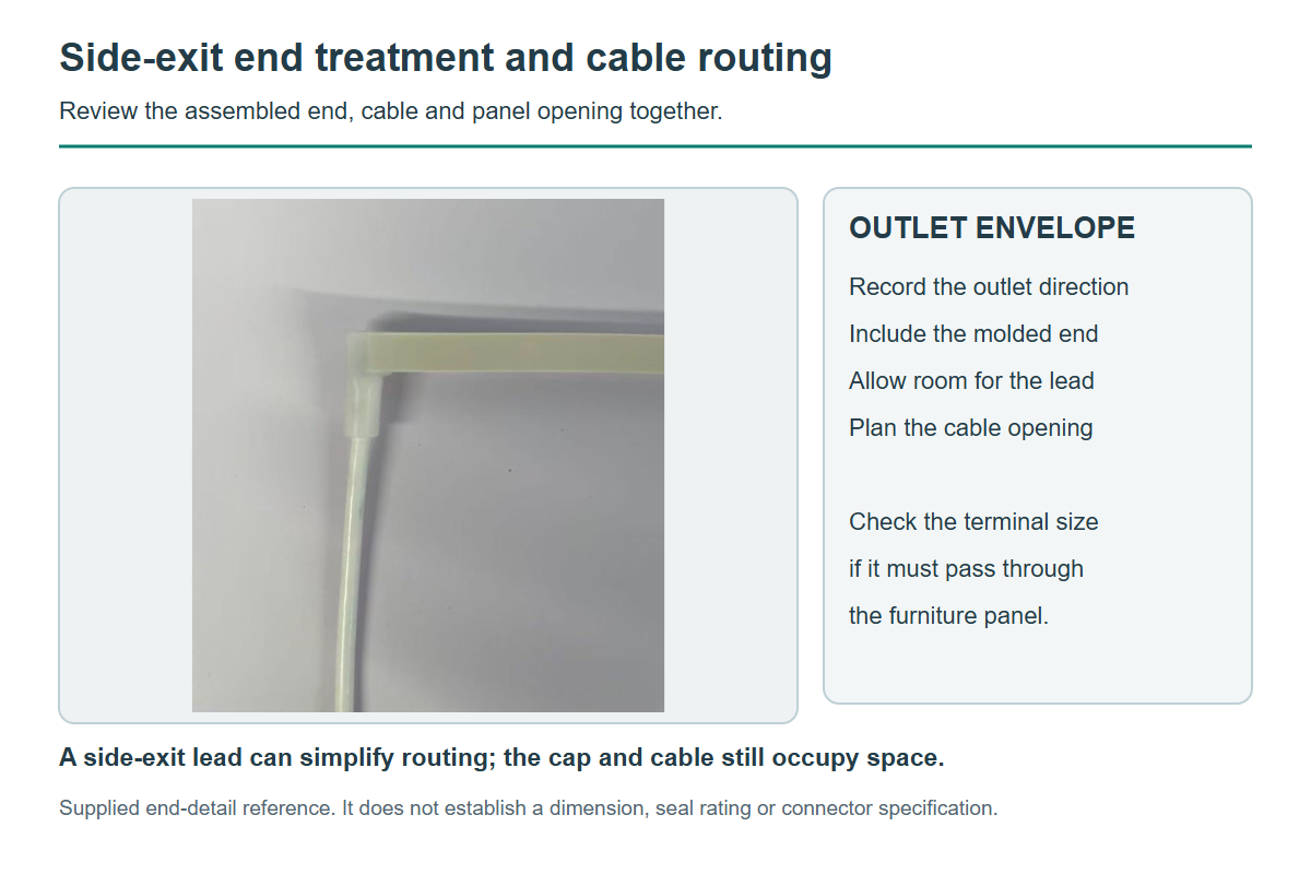
Supplied side-exit end reference. The molded end and cable route need their own space even when the end treatment is matched to the body width. Select the figure to view the full-size image.
The engineering notes identify the cable opening as an often-missed detail. Size and position it for what must actually pass through. If a pre-fitted terminal has to pass through the panel, checking only the cable diameter is insufficient. Allow access for assembly and the intended routing without pulling on the end treatment.
Evaluate the real appearance where the ends meet
“End-to-end” can describe the two ends of one strip meeting around a perimeter, or the end of one strip meeting a second strip. In either case, bringing the bodies together is a physical layout decision. It does not define how the strips are electrically connected.
The supplied engineering observation is clear: the rounded corner was visually uniform, while the capped end junction retained an interruption and a dark region. The caps contain non-emitting space, so a side-exit lead can improve routing and end positioning without making that region disappear.
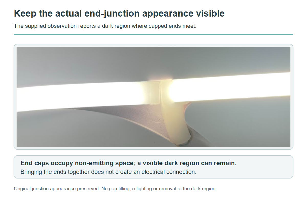
Supplied end-junction reference, with the original light appearance retained. The engineering notes confirm a visible interruption at the capped ends; side-exit routing does not eliminate that non-emitting region. Select the figure to view the full-size image.
Review the junction in the intended viewing position and record whether its appearance meets the project's acceptance requirement. Do not promise a seamless luminous loop from a close physical fit. Preserve the actual junction in approval photographs rather than editing out the gap or dark area.
What the supplied assembly review established
Reported observations and their limits
| Review item | Supplied observation | What it establishes |
|---|---|---|
| Retention | The installed light remained in position without falling out. | An assembly observation for the reviewed sample; no quantified retention force or cycle result was provided. |
| Rounded corner | The corner illumination was described as uniform. | A visual observation; no illuminance map or numerical uniformity limit was provided. |
| End junction | Light continuity was interrupted at the capped ends. | The junction dark region remains part of the appearance to review. |
Keep these observations separate from formal electrical, thermal, environmental or endurance testing. A sample that fits and illuminates a corner does not by itself establish all operating limits or acceptance in another fixture.
Information to release with the sample drawing
- Path and orientation: the installation route, emitting face, permitted bending plane and radius definition.
- Groove: width, depth, tolerance, corner geometry and intended retention method.
- Ends: each cap or lead treatment, assembled envelope and location of the visible junction.
- Cable route: outlet direction, hole position and size, lead length, terminal passage and connection access.
- Appearance approval: representative illuminated views of the corner and capped end junction.
- Product and revision: the approved part drawing and the mechanical and electrical specifications for the selected assembly.
Approve the sample with these details together before repeating the layout in production. A change to the end cap, cable outlet, product construction or groove can require another fit and appearance check.
Frequently Asked Questions
Can 8x8 neon be folded around a sharp 90-degree corner?
The nominal 8x8 size does not establish that capability. Use a permitted bend in the selected product's approved plane and radius. The rounded route in this note is not an instruction to make a sharp fold.
Does a side-exit lead eliminate the end-junction dark region?
No. It can help route the lead and position the ends, but the supplied observation still identifies non-emitting space at the capped ends.
Should every 8x8 neon installation use an 8.2mm groove?
No. The supplied sketch uses 8 + 0.2mm references for its illustrated configuration. The selected body and end dimensions, panel tolerance, installation method and sample fit determine the released groove.
Does putting the two ends together make a closed electrical loop?
No. Physical adjacency does not specify an electrical connection. Define the supply and wiring separately for the selected assembly.
Why must the outlet hole be planned with the connector?
The connector or finished terminal may need to pass through it. Confirm the installed route and assembly sequence before setting the opening size and position.
Related resources and products
- Retail Shelf & Display Lighting Solutions
- Custom LED Strip Engineering
- Testing & Validation
- LED Neon Strips
Review Your Neon Installation Path
Send the path drawing, groove dimensions, corner geometry, end locations and proposed cable route to inquiry@ipixelleds.com. iPixel can review the product construction and end treatment against the intended display-fixture assembly.