
Custom COB LED Strip Solution for High-Density Linear Lighting Applications
COB LED Strips for Slim Profiles and Narrow Spaces
COB LED strips can produce a visually continuous line of light, making them useful for shallow aluminum profiles and compact cabinet or display assemblies. Their closely spaced LED chips and continuous encapsulation reduce the visible points of light often associated with conventional LED strips. For white COB strips, a phosphor-containing layer also converts and blends the light from the chips.
This gives product designers more freedom when there is little room between the light source and the diffuser. A shallower lighting assembly may become practical, provided that brightness, temperature and mechanical fit are verified together. This guide explains what creates the effect and how to evaluate it for an OEM product.
Why COB LED strips look continuous
COB stands for Chip on Board. In a COB strip, LED chips mount directly onto the flexible circuit board rather than arriving as separate, individually packaged LEDs. Many flexible COB designs use flip-chip construction, which makes the electrical connections without the fine bonding wires found in some other LED packages.
For common phosphor-converted white COB strips, closely spaced chips sit beneath a continuous layer of encapsulant containing phosphor. The phosphor converts part of the blue light into longer wavelengths, producing white light in combination with the remaining blue light. Close chip spacing and the continuous emitting layer help reduce visible differences between neighboring light sources.
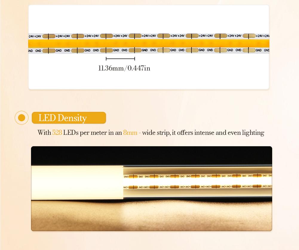
The resulting appearance is often described as “dotless.” It means individual LED points are difficult to distinguish under the intended viewing conditions. It does not guarantee perfect uniformity at every distance or brightness setting. Coating consistency, chip spacing, electrical supply and the finished optical assembly still affect the result. RGB and other color-changing COB designs may use different encapsulation and color-mixing arrangements.
How continuous light helps with slim aluminum profiles
With discrete LEDs, a diffuser needs enough space to spread and overlap the light from neighboring emitters. When it sits too close to widely spaced LEDs, bright points may remain visible through the cover. Using a deeper channel or a more diffusing cover can help, but either choice can affect the product's dimensions or delivered light output.
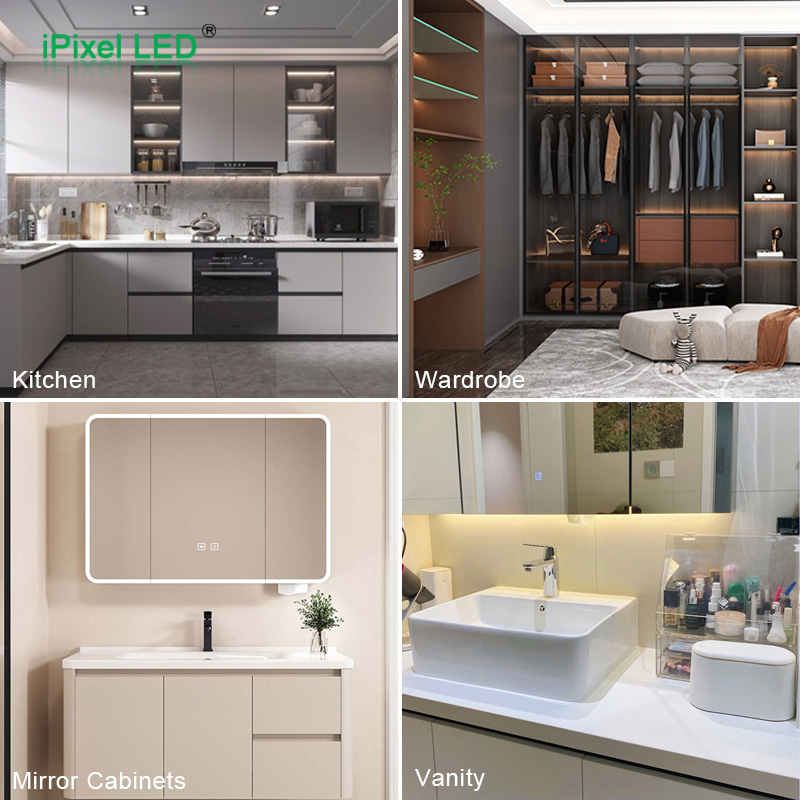
A COB strip starts with a more continuous emitting surface. This can reduce the optical mixing distance needed to achieve an acceptable appearance. Designers can therefore evaluate shallow aluminum channels for shelf edges, wardrobe grooves and cabinet details where a deeper housing would be difficult to conceal.
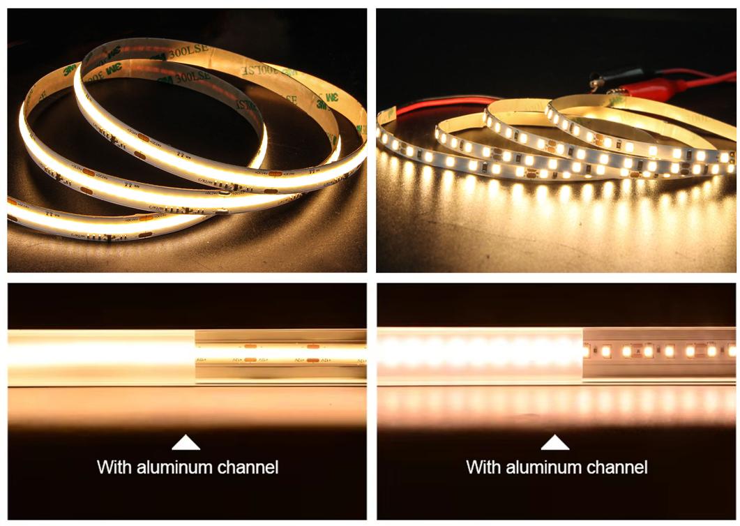
There is no universal minimum profile depth for COB. The distance from the emitting surface to the cover matters more than the external height of the profile alone. Cover material, transmission, internal geometry and the customer's viewing position must also be considered.
For example, when a wardrobe manufacturer wants a light fitting that sits close to the shelf surface, the useful comparison is between complete assemblies: the selected strip, the actual channel and the intended cover. A photograph of an uncovered strip cannot establish the minimum channel depth for that product.
A shallow profile still needs thermal validation
A shorter optical mixing distance does not remove the need to manage heat. The circuit board, adhesive interface, aluminum section and surrounding furniture all influence operating temperature. A low-profile channel enclosed in a wooden groove may behave differently from the same channel tested in open air.
Measure the assembly at its intended power after temperatures stabilize. Use the temperature measurement point and limits specified for the selected strip. If the assembly runs too hot, review power, mounting contact, aluminum section or ventilation before approving the profile.
Narrow installation spaces require the right physical dimensions
The visual benefit of COB and the physical width of a strip are separate considerations. A narrow COB model may fit a compact groove, but the COB construction itself does not guarantee a narrow finished assembly.
Check the usable channel width against the widest part of the lighting system. Connectors, solder joints, cables, end caps and protective encapsulation can require more space than the bare PCB. Leave the assembly clearance specified by the mechanical design rather than making the groove exactly equal to the nominal strip width.
Cutting length matters as well. Dense chips do not mean that every strip can be cut anywhere. Standard products must be cut at their designated positions. Where a short shelf or cabinet opening needs a closer fit, evaluate a suitable short-cut model or a custom length and termination arrangement.
Flexible strips also have bending limits. Follow the specified bending direction and minimum radius, and avoid twisting or creasing the strip to force it around a corner. A wired connection or a different lighting structure may be more suitable for a sharp change in direction.
Where these benefits matter for OEM products
Wardrobes and kitchen cabinets
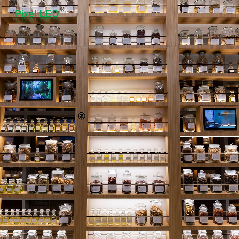
Wardrobe side panels, shelf undersides and recessed cabinet details often leave limited space for the light fitting. COB can help create a continuous visible line in these locations. The assembly should also be evaluated with the chosen door sensor or dimmer, especially at low output levels.
For kitchen work areas, check the light reaching the work surface and reflections in glossy finishes. A smooth-looking source can still be uncomfortable when it is bright and directly visible. Recessing the channel, changing its angle or adding shielding may be necessary.
Retail displays and shelving
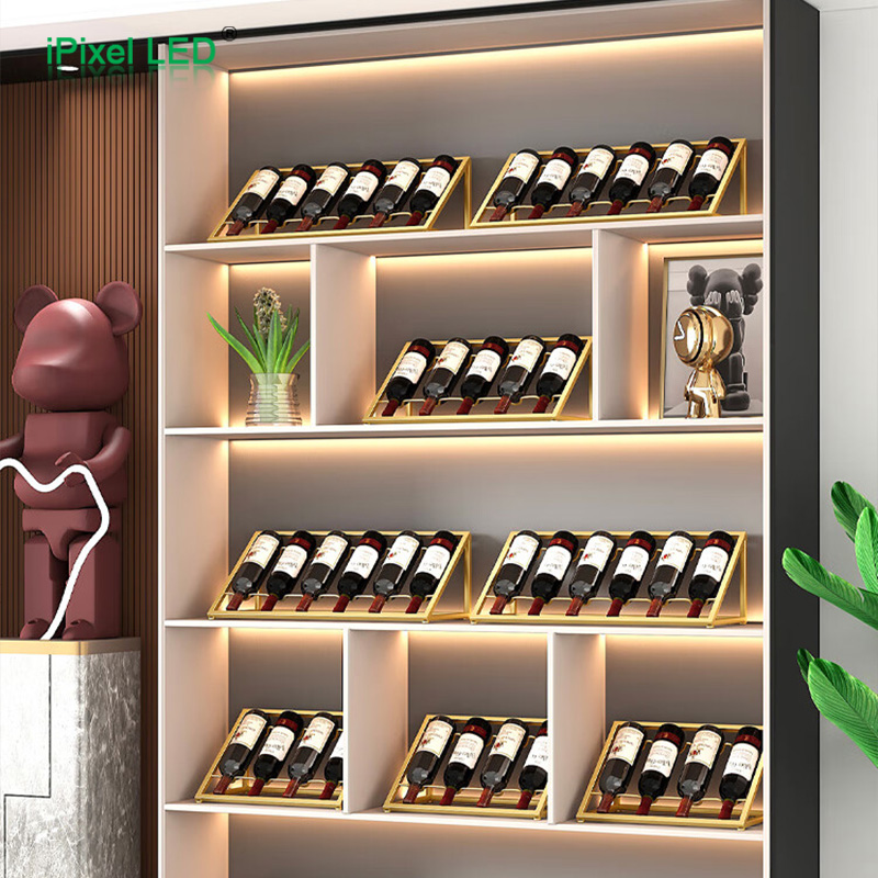
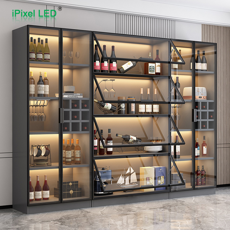
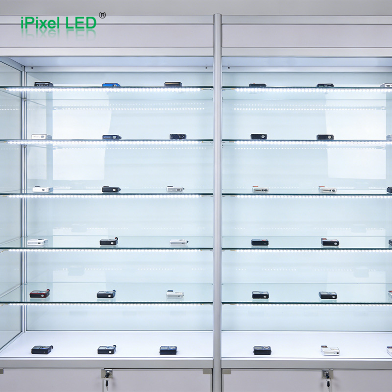
A continuous source can help reduce repeated bright reflections in nearby glass or glossy display components. Narrow models can also be considered where the light fitting must stay within a small shelf edge or display frame.
Assess the illuminated merchandise as well as the strip itself. Shelf spacing, mounting angle, surface finish and any acrylic light guide influence the final distribution. COB cannot by itself eliminate dark areas caused by an obstructed beam or unsuitable light-guide design.
Refrigerated displays
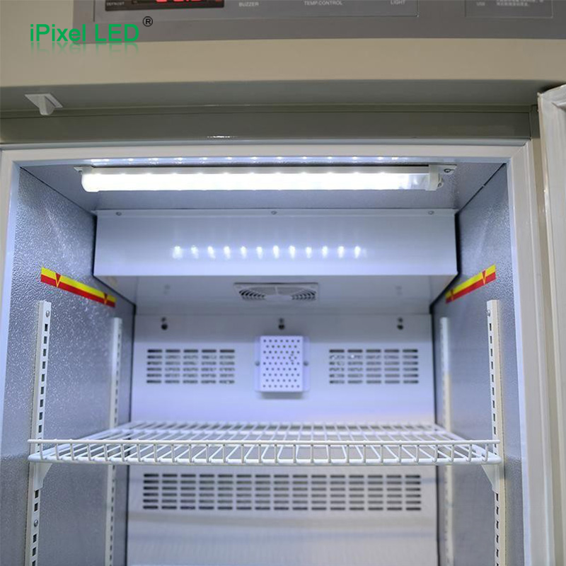
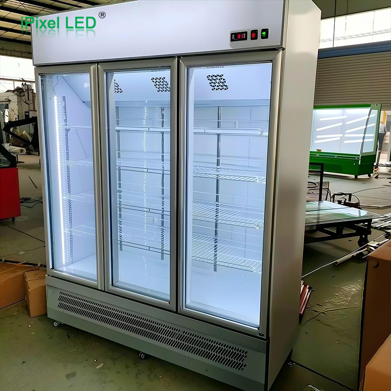
COB may be an option when a refrigerated display needs a continuous decorative or illumination line. However, selecting the light source is only part of the design. Low-temperature operation, condensation during door openings, cleaning exposure and sealed cable exits need application-specific validation.
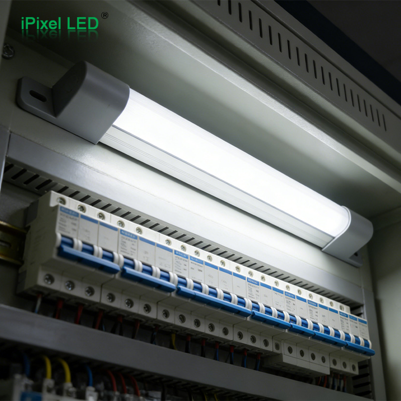
A phosphor coating is not a waterproof system. The protection of the complete assembly, including cut ends and connectors, must match the environment. Depending on mounting and beam requirements, a sealed rigid light bar may be a better fit for a refrigeration project.
A specification checklist for compact COB assemblies
| Design factor | What to confirm | Why it matters |
|---|---|---|
| Mechanical fit | Finished strip width and height, usable channel space, cable exit and end caps | Prevents a nominally narrow strip from becoming an oversized assembly |
| Optical spacing | Emitting surface to diffuser distance, cover type and viewing angle | Determines whether visible points remain |
| Light output | Required illuminance at the target surface and output after the cover | Avoids judging useful brightness from the bare strip alone |
| Color quality | CCT, CRI and agreed color consistency across samples and batches | Helps match adjacent shelves and repeat production |
| Electrical design | Rated voltage, power per meter, run length, wiring and control compatibility | Supports consistent brightness and stable dimming |
| Thermal design | Mounting interface and stabilized temperature in the final enclosure | Establishes whether a slim profile is suitable at the selected power |
| Cutting and assembly | Cut interval, finished length, bend limits and connector clearance | Reduces dark end gaps and installation damage |
| Environment | Temperature, moisture, cleaning agents and complete sealing arrangement | Defines the materials and testing needed for the application |
For broader platform selection, see our SMD vs COB LED strip guide. For long shelf runs, also review LED strip voltage drop.
How to validate a shallow-profile sample
- Define the acceptance conditions. Record the expected viewing distance, viewing angles, ambient lighting and brightness settings. Agree which visible dots, end gaps or color differences would be unacceptable.
- Build the actual assembly. Use the intended profile, cover, adhesive, cables, power supply and controller. Include any protective coating and end treatment that will be used in production.
- Inspect direct and reflected light. Look at the cover and the illuminated surface. Include nearby glass, polished metal or glossy cabinet finishes. Check joints, cut points and both ends of the assembly.
- Test the electrical and thermal conditions. Run the intended maximum length and output until temperatures stabilize. Check the far end for brightness changes and test the required dimming range.
- Record an approved reference. Save the assembly drawing, component details and acceptance observations. Photographs should use controlled exposure and white balance: an overexposed image can hide visible points of light.
This process turns “dotless” into an agreed product requirement. If the first sample does not pass, change one relevant variable at a time, such as optical spacing, cover, strip selection or mounting angle, and repeat the comparison.
Manufacturing details that influence the result
Chip attachment, solder quality and dispensing consistency all affect COB performance. For phosphor-converted white strips, the mixture and thickness of the coating need control to support consistent color and appearance. Curing, handling and protection during assembly also matter because damage can affect the encapsulation or electrical connections.
Flip-chip construction removes a wire-bond failure mechanism where that construction is used. It does not prevent every electrical failure. The effect of a failed chip depends on the circuit and failure mode, while contamination and unsuitable chemicals can still affect materials. Product lifetime, efficiency and environmental resistance should be evaluated using the selected product's data and relevant test results.
Frequently asked questions
Do COB LED strips always need a diffuser?
Some COB strips can look continuous without one. A cover may still be useful for light distribution, glare control, cleaning or physical protection. Decide using the final installation and its protection requirements.
Can COB work in an ultra-thin aluminum profile?
It can make a shallower optical assembly possible, but suitability depends on the chosen strip, cover, spacing and temperature. Confirm the combination with a sample before fixing the profile dimensions.
Does a higher chip density always give better results?
Higher density can help reduce visible spacing, but coating consistency, power, optics and electrical design also influence the result. Compare complete assemblies against the same visual requirement.
Is dotless lighting the same as glare-free lighting?
No. Dotless describes the visibility of individual light points. Glare also depends on brightness, viewing angle, shielding and the surrounding environment.
Can every COB strip be cut to any length?
No. Follow the cutting instructions for the selected model. A short-cut or specially designed free-cut product must be evaluated according to its own specification.
Is COB automatically suitable for a cold cabinet?
No. The strip and complete assembly must be selected for the temperature, condensation and cleaning conditions. Sealing, wiring and mechanical protection require separate attention.
Discuss your COB lighting assembly with iPixel
iPixel supports custom LED strip and lighting module projects for OEM manufacturers. To evaluate a compact COB solution, share your groove or profile drawing, finished length, voltage, target brightness, color requirements and operating environment. Include a photo or description of the required viewing conditions so the sample can be assessed against a clear visual target.
Explore our COB LED strip range or contact iPixel to discuss your project.