
How to Select the Right 3M LED Tape for Reliable LED Strip Installation
The right adhesive backing for an LED strip depends on the two surfaces being joined, the temperature at the bond line, the load on the joint and the installation process. A 3M logo on the release liner does not identify the complete tape construction or establish that it suits your application.
For smooth metal surfaces, thin acrylic transfer tapes may be candidates. Low-surface-energy plastics and some powder coatings need a different adhesive approach. Silicone surfaces require particular attention to adhesive chemistry. Where heat must pass from a circuit board into an aluminum heat sink, evaluate a specified thermal interface rather than choosing tape only by its peel strength.
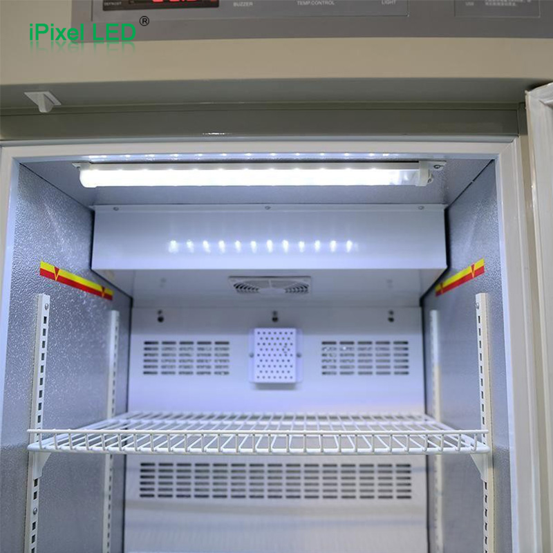
This guide covers flexible LED strips and bare rigid LED boards that use adhesive mounting. Mechanically mounted, enclosed refrigeration light bars are outside its main scope. The product examples below are candidates for testing, not approved substitutions or a guarantee for every LED assembly.
Start with the two surfaces, not the industry name
A wardrobe, vending machine and display cabinet may all contain painted metal, plastic and aluminum. Conversely, two apparently identical aluminum channels may have different anodizing, paint or surface contamination. The adhesive touches the finish, not simply the material named on the drawing.
Identify both interfaces in the lighting assembly:
- LED strip or board to its support: the actual bonding surface may be a flexible PCB coverlay, solder mask, aluminum PCB back, protective coating or silicone jacket.
- Support to the finished product: an aluminum profile may then attach to coated steel, a furniture panel, glass or a plastic housing. This is a separate joint, carrying a different load and potentially requiring a different tape.
For example, an LED strip bonded inside an aluminum channel and the channel bonded beneath a shelf should not automatically use the same backing. The first joint may need a thin thermal path; the second must support the channel and resist installation or service loads.
Why LED strip adhesive fails
Most failures need more investigation than “the tape was not strong enough.” Inspect the separated surfaces before cleaning them or replacing the tape.
| What you observe | Possible causes to investigate | What to check next |
|---|---|---|
| Tape stays on the strip but releases from the channel | Contamination, poor surface compatibility, insufficient contact or unsuitable application temperature | Channel finish, cleaning process, application pressure and temperature |
| Tape stays on the channel but releases from the strip | PCB-side adhesion problem, coating incompatibility or weak factory lamination | Actual strip backing material and supplier lamination process |
| Paint, wood fibers or a coating comes off with the tape | The substrate layer is weaker than the adhesive joint | Coating adhesion, panel preparation or a mechanically fixed profile |
| Ends lift first | Cable pull, bending recovery, local heat or a peel load | Strain relief, bend geometry, end retention and hot spots |
| Strip slowly moves or sags | Sustained load and adhesive creep, often aggravated by heat | Loaded hot dwell test in the real orientation |
| Bond passes initially but fails later | Moisture, cleaning chemicals, migrating additives, thermal cycles or accumulated stress | Exposure history and aged samples, not just a fresh peel test |
These observations are diagnostic clues. They do not prove a root cause without examining the materials and assembly conditions.
A practical selection route by mounting surface
Smooth aluminum and other clean metal surfaces
Thin transfer tapes can be considered when the mating surfaces are flat and offer good adhesive contact. A transfer tape has adhesive without a permanent film or foam carrier. A film-backed double-coated tape may be easier to convert and handle, but adds a different layer to the assembly.
3M's product guidance identifies 467MP and 468MP as 200MP-family transfer tapes for high-surface-energy bonding. They differ in thickness and should not be treated as identical. Evaluate the actual metal finish and the PCB-side surface together. See the 3M thin bonding product guide.
Powder-coated metal and difficult plastics
PP and PE are examples of low-surface-energy plastics. Some powder coatings are also difficult to bond. The finish formulation, texture and release agents can matter as much as the base material.
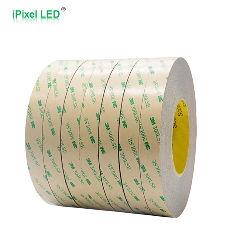
3M identifies 300LSE as an adhesive family intended for difficult surfaces, while 200MP is not the default choice for low-surface-energy substrates. A product such as 9495LE can therefore be a candidate for trials on suitable plastics or powder-coated surfaces. This does not establish compatibility with every plastic, coating or textured panel. See 3M surface selection guidance.
Furniture panels, wood and textured finishes
For wardrobes, cabinets and bed frames, identify whether the surface is melamine, laminate, cured paint, veneer or unfinished wood. A tape cannot create a reliable joint if the surface fibers or coating detach. Deep texture also reduces the area actually touching the adhesive.
A mechanically secured aluminum profile may provide a more controllable mounting surface than direct bonding to an unfinished panel. Where a sealer or primer is proposed, qualify the complete treatment with the panel supplier and adhesive supplier. Adding primer is a process change, not a universal repair for poor adhesion.
Glass, mirror backs and bathroom surfaces
Clean glass and a mirror's rear protective paint are different bonding surfaces. Check the mirror manufacturer's compatibility requirements before attaching anything to the backing. Humidity and cleaning exposure should be included in the joint evaluation; a good dry-room bond does not prove suitability for repeated condensation.
Silicone jackets and flexible PVC
Silicone is not interchangeable with an ordinary plastic surface. A tape with silicone adhesive on one face and acrylic adhesive on the other, such as an appropriate 9731 variant, may provide a starting point when the two mating materials differ. The silicone adhesive face must be oriented to the intended silicone surface. Confirm the exact variant and winding direction with the converter. See 3M 9731 product information.
For plasticized PVC, request compatibility testing for additive migration. For a flexible or curved jacket, also check spring-back and peel forces. A mounting clip or channel may be necessary even if a flat sample shows good adhesion.
Which 3M tape types are worth evaluating
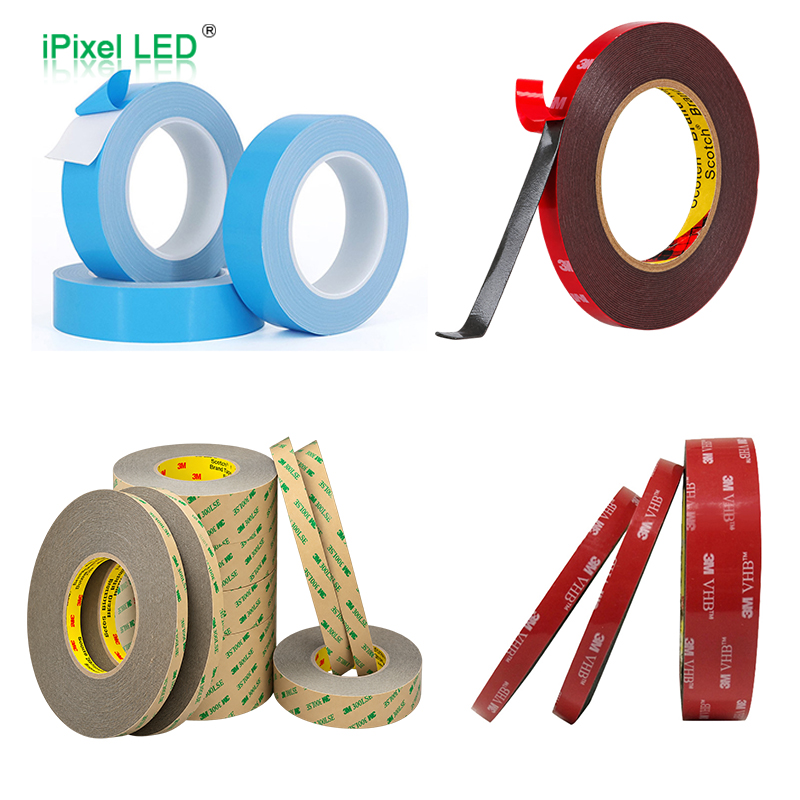
This table is a shortlist by function. It does not replace the technical data sheet for the exact supplied product, thickness, suffix and market. None of these entries establishes an LED-system temperature rating.
| Product or family | What it represents | Candidate use and selection boundary |
|---|---|---|
| 467MP / 468MP | Thin transfer tapes using 200MP adhesive | Trials on smooth compatible metal or high-surface-energy surfaces; confirm thickness and both bonding faces |
| 9495LE | Film-backed double-coated tape using 300LSE adhesive | Trials on suitable difficult plastics and powder coatings; texture and chemistry still require testing |
| 9448A | Tissue-backed acrylic double-coated tape | A handling-friendly candidate for compatible surfaces; general adhesion does not establish a thermal interface or outdoor lifetime |
| 9080HL | Non-woven double-coated acrylic tape | A converting and bonding candidate; use its own data rather than treating it as interchangeable with 9448A or 9080A |
| 9731 variants | Different adhesives on opposite faces: silicone and acrylic | Joining suitable silicone surfaces to a compatible second substrate; variant and face orientation are critical |
| VHB 5952 and other selected VHB grades | Acrylic foam bonding tapes | Evaluate for a profile-to-panel joint where compliance is useful; thickness, load and available space govern selection |
| VHB GPH grades | Acrylic foam grades developed for elevated-temperature demands | Consider only within a verified joint design; a short heat exposure rating is not an LED operating approval |
| 8805 / 8810 | Thermally conductive adhesive transfer tapes | Candidates for a board-to-heat-sink interface; check thermal resistance, contact quality, retention and electrical requirements |
Product construction references: 9495LE, 9448A, 9080HL, VHB selection guide and 8800-series technical data.
200MP, 300LSE and 100MP are adhesive family names. They are not complete purchase specifications. Likewise, “VHB,” “automotive tape” and “3M backing” do not specify a unique product. Record the full part number and approved construction on the bill of materials.
Adhesion, heat resistance and thermal conductivity are different
Adhesion describes how the joint holds the parts together. Heat resistance describes performance under specified temperature and exposure conditions. Thermal conductivity describes how a material conducts heat. A tape advertised as heat-resistant is not automatically a thermally conductive tape.
For a uniform layer, the simplified through-thickness thermal resistance is R = t / (k × A), where t is thickness, k is thermal conductivity and A is effective contact area. This relationship shows why a thicker bond line can increase resistance when the other factors are unchanged. Actual assemblies also include contact resistance, surface flatness, voids and heat spreading through the board.
3M lists 8805 and 8810 in its thermally conductive tape family, intended to provide a heat-transfer path to cooling structures. Select the interface by its documented properties and verify the powered assembly. Bonding a thermal tape to wood or plastic does not create the heat-spreading capacity of an aluminum heat sink. See 3M 8810 application information.
For bare rigid LED boards, inspect backside conductors, solder protrusions, flatness and electrical isolation requirements. A thermally conductive tape is not automatically an approved electrical safety barrier. Where reliable thermal contact and retention are both important, consider a designed interface with mechanical attachment rather than assuming an adhesive-only joint will be sufficient.
Avoid adding generic foam tape between a heat-generating board and its intended heat sink without checking the temperature effect. A more compliant mounting layer may solve a mechanical problem while worsening the thermal path.
Match the validation to the application
The industry name helps identify exposure conditions; it does not select the tape by itself. The following are proposed checks for adhesive-mounted lighting, not claims that these applications have already been qualified.
| Application | Conditions that change the decision | Mounting and verification priorities |
|---|---|---|
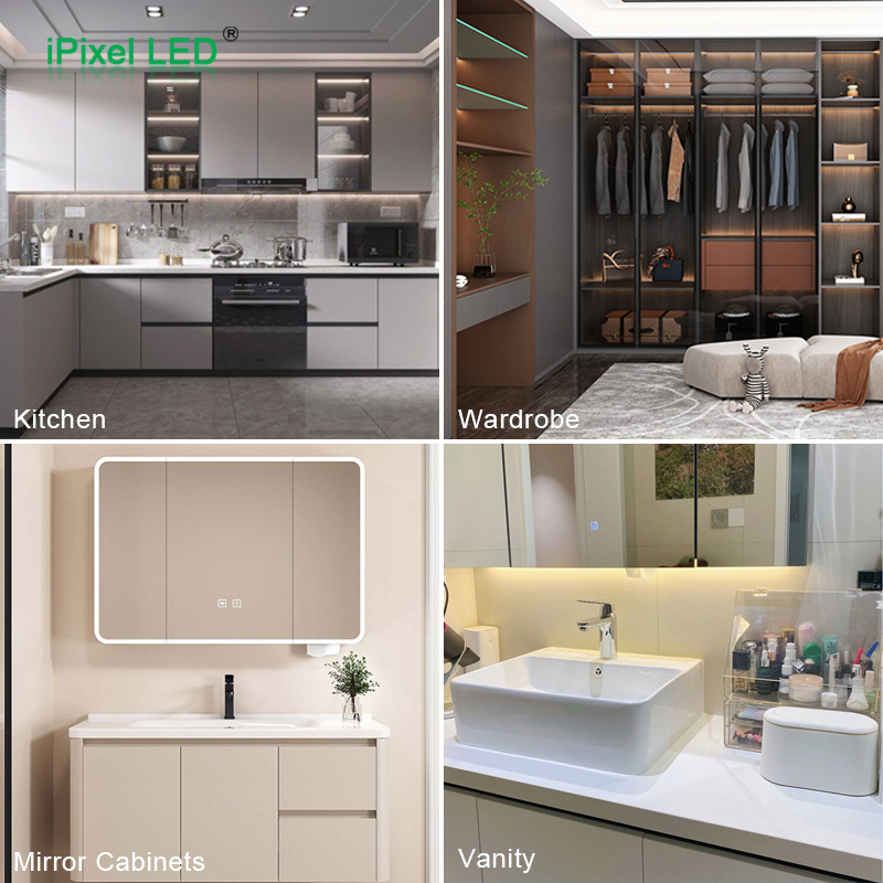
| Wardrobes, kitchen cabinets and bed frames | Panel finish, dust, underside installation and cable routing | Check the actual finish, end lift and sustained load; consider fixed profiles for unreliable panel surfaces |
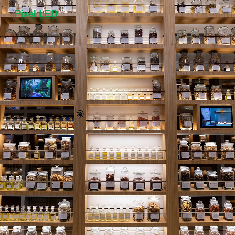
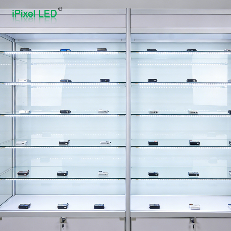
| Retail shelving, display cabinets and non-refrigerated wine displays | Powder coating, acrylic parts, visible joints and frequent cleaning | Test production coating batches and cleaning agents; account for profile weight and replacement access |
| Mirror and bathroom cabinets | Humidity, condensation and mirror-back coatings | Confirm material compatibility and repeated moisture exposure; do not treat backing tape as the enclosure seal |
| Pharmacy cabinets | Cleaning or disinfecting routines, service access and traceability needs | Test the actual cleaner and contact time; record tape lot and installation process; do not infer medical qualification |
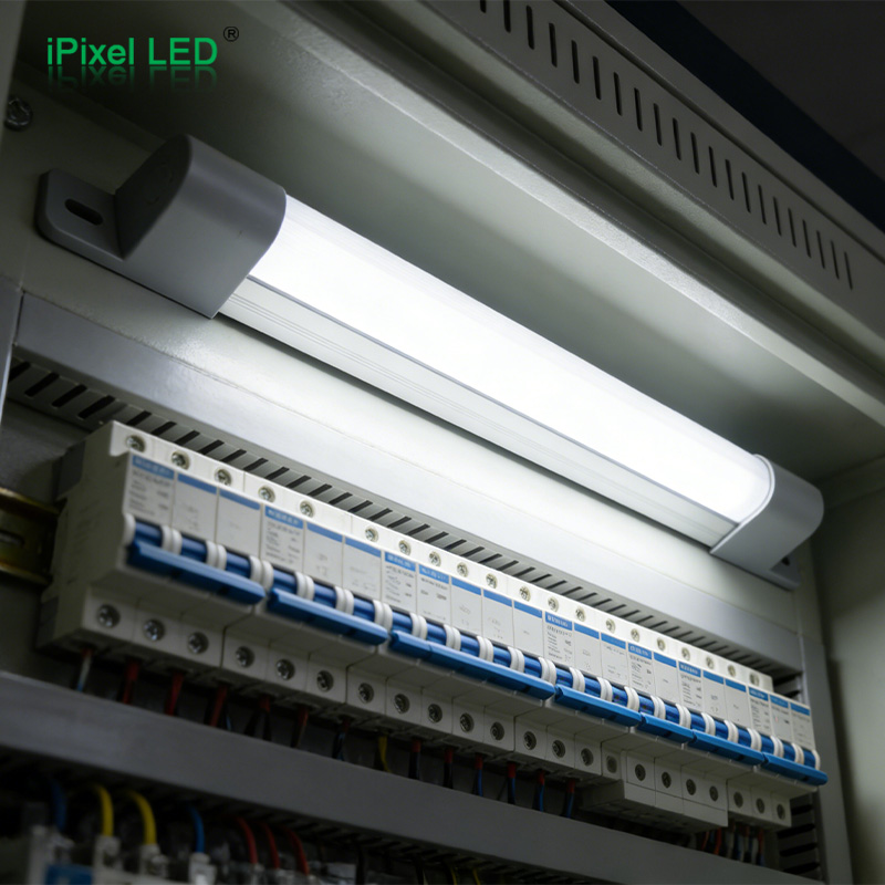
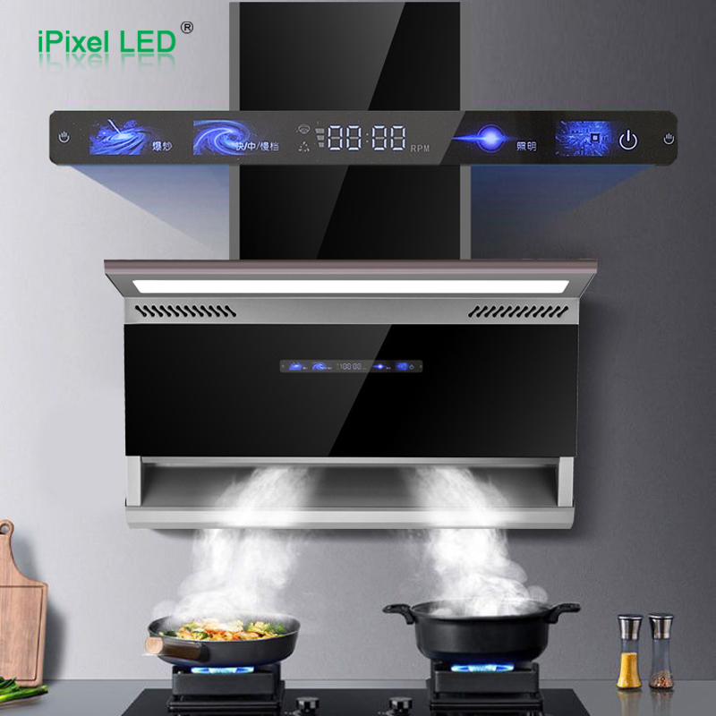
| Range hoods and industrial cabinets | Hot spots, grease, oil mist, vibration and cleaning chemicals | Measure the bond-line temperature and test loaded hot samples; assess positive mechanical retention |
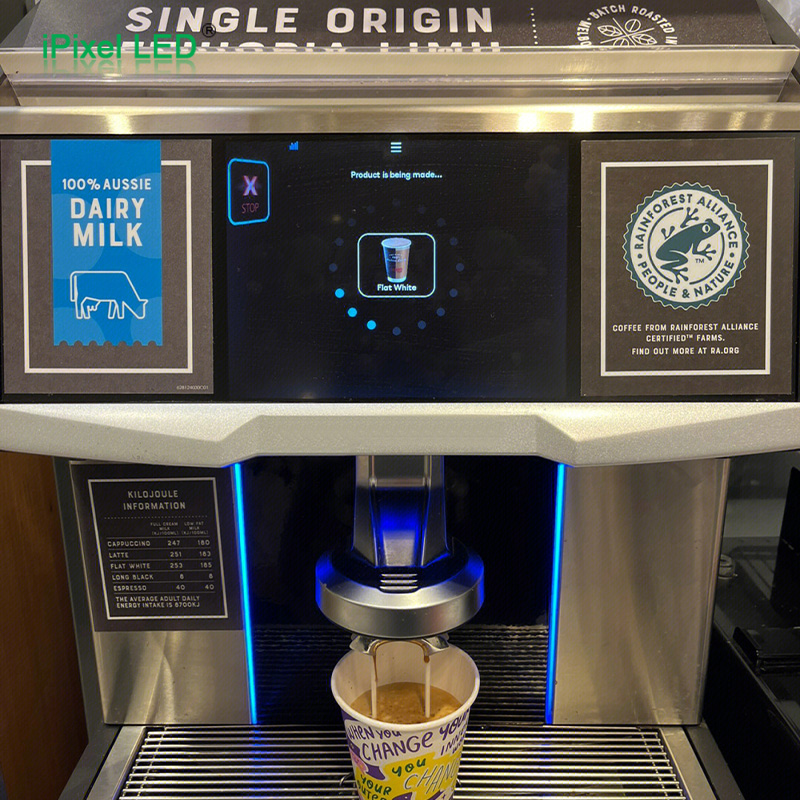
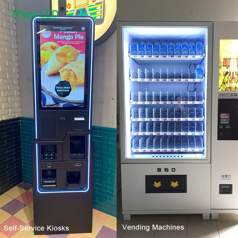
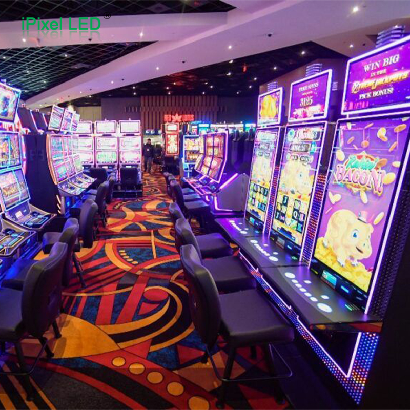
| Vending machines, kiosks, arcade and slot machines | Transport vibration, door impacts, maintenance and enclosed heat | Provide cable strain relief, test representative vibration and service cycles, and inspect inaccessible joints |
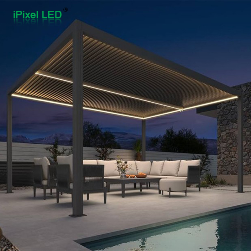
| Outdoor umbrellas and related lighting frames | Sun heating, water, UV exposure, folding and flexing | Test weather exposure and repeated movement; retain strips in suitable channels or clips where needed |
| Vehicle-related LED assemblies | Vibration, thermal cycles, different plastics and customer specifications | Qualify the exact joint to the customer's application requirements; an automotive label alone is insufficient |
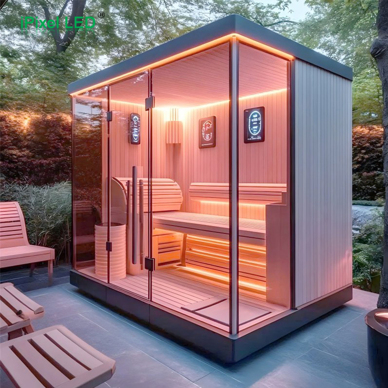
| Electric fireplaces and sauna or SPA rooms | Local radiant heat, prolonged heat, humidity or steam | Confirm that the complete lighting assembly is suitable first; use temperature mapping and retention testing |
| Adhesive-mounted strips in refrigerated or wine cabinets | Cold starts, condensation, defrost and cleaning | Install on dry surfaces within the tape's application window, then test cold and moisture cycles; enclosed mechanically fixed bars need a different mounting review |
Medical refrigerators are included only if they actually contain an adhesive-mounted strip or board. Their conventional enclosed rigid light bars are not a reason to add unnecessary tape selection advice.
Installation conditions can make or break the bond
Separate application temperature from service temperature
Application temperature is the temperature during bonding. Service temperature is the temperature after the joint has developed and the equipment is operating. A tape that can survive cold service may still need warmer, dry surfaces to form a good initial bond. Also distinguish brief process heat from prolonged service under load.
Measure the local joint temperature with the LEDs powered and the product closed as it will be used. Room temperature, air temperature inside the cabinet and adhesive bond-line temperature can be different.
Use a controlled assembly sequence
- Verify materials and tape identity. Record the exact tape, lot, storage history, finished width and actual surfaces. Inspect for damaged liner, contamination or expired material according to the supplier's stated shelf life.
- Prepare compatible surfaces. Remove contamination using an approved cleaning method, then let the surfaces dry. Check cleaner compatibility with plastics, painted finishes and LED encapsulation. Do not apply over moisture, loose coating or manufacturing residue.
- Apply without stretching or forced bending. Align the strip without storing a spring-back force in it. Avoid touching the adhesive and do not assume lifting and reapplying preserves the original bond.
- Create uniform contact. Use a supported method that reaches the bond area without crushing LEDs, solder joints or COB encapsulation. Validate the pressing tool for the lighting construction.
- Allow bond development before loading. Follow the exact tape's process and support the assembly while required. Factory lamination to the strip and final installation on the customer surface are separate bonding events.
- Relieve cable and end loads. Secure wiring so connector handling does not pull the strip away. Check corners and ends, where local peel loads can concentrate.
For context, 3M's VHB surface-preparation guidance describes firm pressure and typical bond development at room temperature of about 50% after 20 minutes, 90% after 24 hours and 100% after 72 hours. These are VHB guidance values, not a universal schedule for every tape listed here. See 3M VHB surface preparation.
When mechanical retention should be part of the design
An LED strip has little mass, but a cable, stiff connector or recovering bend can impose a substantial local peel force. A long, narrow bond also behaves differently from the broad test specimen used for a catalogue value. Do not multiply a published peel result by tape length to calculate a safe supported weight.
For overhead installations, moving structures, hot enclosures, frequent service or locations where detachment could damage the product, assess clips, a retained channel or suitable fasteners. Mechanical retention can also keep a board seated against its thermal interface. Size and place it without damaging conductors or violating the board's mounting instructions.
If the lighting must be replaced, decide how it will be removed and reinstalled. A high-strength permanent bond may make field service harder or damage the finished panel. Serviceability belongs in the original selection brief.
Qualify the complete assembly before volume production
Start with small coupons of the actual strip backing and production mounting surface. Compare candidate tapes under controlled preparation and dwell conditions. Then test representative lighting assemblies, including their final length, orientation, cable routing and powered heat load.
Agree the test conditions and acceptance limits before the trial. Useful checks include sustained hot load, thermal cycling, humidity or condensation, actual cleaning exposure, vibration or repeated movement, and end-lift inspection. Choose the exposure duration, number of samples and severity from the product's service requirements and customer specification; a generic short trial cannot establish years of life.
Record displacement or edge lift, changes in electrical operation, temperature and the location of any failure. Inspect after aging, not only while the adhesive is new. Distinguish failure at either interface from cohesive adhesive damage or separation of the substrate finish.
Retest after changes to tape grade, thickness, converter, PCB coating, panel finish, cleaner or assembly process. Freeze the approved combination and record traceability for repeat orders. A different backing is a material change even if it looks similar.
What to send your LED supplier
Provide the strip or board drawing, both bonding surface specifications, the installed orientation, available bonding width, local temperature range and expected exposure. Include photos of the actual surface and describe cleaning, vibration, moisture, cable loads and replacement requirements.
Ask for the exact tape designation, applicable technical data sheet, factory lamination method and proposed qualification plan. If “3M backing” appears on the quotation, ask which part number and construction it means. Supplier documentation and lot traceability matter more than the printed liner alone.
Frequently asked questions
Is 3M 300LSE a complete tape model?
No. It identifies an adhesive family. The full tape designation determines the carrier, thickness and other construction details. Confirm the exact product being supplied.
Is VHB always better than thin tape for LED strips?
No. A foam construction may help accommodate movement or irregularity in one joint, but add unwanted thickness or thermal resistance in another. Evaluate the specific joint rather than ranking tapes by brand family.
Can the same tape be used on aluminum, plastic and wood?
Sometimes a candidate can work on several surfaces, but each actual finish and exposure still needs validation. Surface chemistry, roughness and substrate strength differ.
Does stronger adhesive solve every falling-strip problem?
No. It cannot correct a loose paint layer, moisture at installation, poor contact, excess heat or a cable pulling the end away. Identify the failure location before changing the tape.
Does a waterproof strip need waterproof backing tape?
The mounting joint must tolerate its environment, but tape selection does not establish the strip's IP rating. Sealing the electronics and retaining the lighting are separate design tasks.
Can tape be applied directly to a cold cabinet wall?
Only if the actual surface condition and temperature meet the selected tape's installation requirements. Cold surfaces may carry condensation even when they appear clean. Cold-service capability does not prove cold-application suitability.
Must every flexible LED strip use 3M backing?
No. Depending on its structure, a strip may use another qualified adhesive, a channel or mechanical retention. Where 3M tape is specified, the exact grade still needs to match the application.
Discuss an adhesive-mounted LED assembly with iPixel
For a custom lighting project, send iPixel the actual mounting surface, drawing and operating conditions along with your electrical and optical requirements. These details allow the backing and installation method to be considered as part of the complete lighting assembly.
Explore iPixel LED products or contact the team about your project. Related engineering considerations are available in our Technical Guides.
3M and VHB are trademarks of 3M. Product references identify candidate materials and do not imply 3M approval of a particular iPixel assembly.