
WS2815 vs SK6813 vs HC2815: An Engineering Guide to 12V Addressable LEDs
Technical reference | iPixel LED | Datasheet-based comparison
Abstract
WS2815, SK6813 and HC2815 are often considered for 12V addressable RGB lighting, but similar package sizes and headline data rates do not establish interchangeability. This technical review compares three specific documented devices: WS2815E, SK6813HV-09-6P-003 and the HC2815-based HC-5050Z1GRB-12V-I6-FS. It examines pin assignments, input thresholds, data timing, color order, PWM frequency and optical specifications, then translates these differences into a practical selection method for OEM engineers. The principal finding is that selection should begin with PCB and controller compatibility, followed by optical requirements and verification of the exact supplied variant. This is a review of supplied specifications and sample photographs, not a report of comparative laboratory measurements.
Keywords: 12V addressable LED; WS2815E; SK6813HV; HC2815; RGB pixel; signal timing; LED selection.
In this guide
- Abstract
- Which device should an engineer choose?
- Scope, source versions and method
- Key specifications at a glance
- PCB compatibility: the same package does not mean the same pinout
- Controller compatibility: check the complete waveform
- PWM frequency, animation frame rate and power
- Optical differences: compare more than the IC name
- What the package photographs show
- A second data input does not establish identical bypass behavior
- Selection matrix for OEM projects
- Frequently asked questions
- Conclusion
- References and source qualifications
1. Which device should an engineer choose?
For an existing design, start with the exact pinout and validated controller profile. For a new design, shortlist by optical output, dimming requirements and firmware flexibility. The reviewed HC2815 and SK6813HV documents specify 8kHz PWM; the WS2815E document specifies a 2kHz port scanning frequency. HC2815 lists higher luminous-intensity ranges for the supplied optical configuration, while SK6813HV specifies RGB rather than GRB data order. None of these facts alone identifies a universal winner. [1–3]
Three practical starting points are:
- Existing WS2815E hardware: preserve the documented VCC/VDD arrangement and pin mapping when evaluating continued use. Moving to either of the other reviewed parts is not a direct pin-for-pin substitution.
- A new design prioritizing an 8kHz PWM specification: evaluate HC2815 and SK6813HV first, then compare the complete light output and controller implementation.
- A new design prioritizing the listed luminous intensity: evaluate the reviewed HC configuration as a candidate, then measure output through the actual diffuser and enclosure. Datasheet mcd values are not finished-strip lumen measurements.
2. Scope, source versions and method
Family names in searches are broader than exact orderable parts. This article uses the short labels below only for readability; its numerical conclusions apply to the listed documents, not automatically to every product carrying a similar name.
| Short label | Exact source covered | Document identification |
|---|---|---|
| WS2815E | WS2815E integrated RGB LED | V1.0, revision record dated 2021-09-23 [1] |
| SK6813HV | SK6813HV-09-6P-003 | Rev. B/0, dated 2024-06-13 [2] |
| HC2815 | HC2815-based HC-5050Z1GRB-12V-I6-FS | Supplied specification dated 2022-09-28 [3] |
Values below are transcribed from the documents and normalized to consistent units. Typical values, limit ranges and test conditions remain distinct. Where a document is incomplete or internally inconsistent, the issue is identified rather than silently corrected. Engineering recommendations are interpretations of those source values, not additional manufacturer guarantees.
The supplied photographs illustrate samples identified by iPixel as WS2815, SK6813 and HC2815. They are not proof of silicon revision, current setting or optical bin, and they do not independently establish that each photographed sample matches every parameter in the corresponding document.
3. Key specifications at a glance
| Parameter | WS2815E [1] | SK6813HV [2] | HC2815 [3] |
|---|---|---|---|
| Nominal supply | 12V | 12V | 12V |
| Supply range as documented | 9.5–13.5V, under “maximum ratings” | 10.8–14.0V in electrical table | 10.8–13.2V in electrical table |
| Package | 5050, 6 pins | 5050, 6 pins | 5050, 6 pins |
| Pixel data | 24 bits, 8 bits per color | 24 bits, 8 bits per color | 24 bits, 8 bits per color |
| Wire color order, MSB first | GRB | RGB | GRB |
| Stated data rate | Up to 800kbps | 800kbps typical | Up to 800kbps |
| Light modulation specification | 2kHz port scanning | 8kHz PWM typical | 8kHz PWM typical |
| Current information | 12mA optical-test current; no comparable drive-current tolerance table | RGB output drive current: 8/9/11mA min/typ/max | RGB output current: 9mA typical |
| Quiescent current | Less than 2.1mA at 12V | 2.0mA typical | 2.0mA typical |
| Listed operating temperature | −25 to +85°C | −40 to +85°C | −40 to +85°C |
| Second input pin | BIN | DIN2 | BIN |
How to read this table: the WS supply entry is printed under maximum ratings, so it should not be treated as equivalent to a guaranteed recommended operating range. The current entries also have different meanings: an optical-test current is not a complete power-consumption specification. Confirm the permitted supply range and current behavior for the production part. [1, pp. 2–3; 2, pp. 5–6; 3, p. 5]
4. PCB compatibility: the same package does not mean the same pinout
| Pin number | WS2815E | SK6813HV | HC2815 |
|---|---|---|---|
| 1 | VCC: IC supply node, with a capacitor to ground in the application circuit | VDD: supply | VDD: supply |
| 2 | VDD: +12V supply | NC | NC |
| 3 | DO | DOUT | DO |
| 4 | DIN | GND | GND |
| 5 | GND | DIN1 | DIN |
| 6 | BIN | DIN2 | BIN |
Sources: [1, pp. 2, 4; 2, pp. 4–5; 3, pp. 4, 10]. Pin numbers follow each source drawing; PCB layout must also respect top/bottom view and package orientation.
The important differences are the supply pins and the exchanged ground/data positions. WS2815E is not pin-compatible with the other two reviewed parts. Its VCC pin must not be assumed to be the same connection as the VDD pin of HC2815 or SK6813HV.
HC2815 and SK6813HV share the listed pin positions, but that is only one condition for substitution. Land pattern, mechanical dimensions, color order, input timing and the operation of the second input still need to match the design. A common footprint alone does not establish a drop-in replacement.
5. Controller compatibility: check the complete waveform
5.1 Supply voltage and signal voltage are different requirements
A 12V supply designation does not mean that 12V should be applied to the data input. HC2815 lists a minimum input-high threshold of 4.0V and maximum input-low threshold of 1.0V. SK6813HV lists the same thresholds, but its test-condition column says VDD = 5.0V despite the device being specified for 12V operation; that condition needs clarification. WS2815E defines the input-high and input-low thresholds relative to VCC, at 0.7 × VCC and 0.3 × VCC respectively. VCC is distinct from its 12V VDD supply. [1, p. 2; 2, p. 6; 3, p. 5]
Consequently, a nominal 3.3V controller output is not shown to meet the HC/SK minimum input-high specification. Do not assume direct 3.3V compatibility from the supply voltage or family name. Select the interface using confirmed input limits, and verify the signal at the receiving LED relative to its local ground.
5.2 Timing comparison
All durations in the following table are in microseconds (µs). T0H/T0L are the high/low portions of a zero bit; T1H/T1L are the high/low portions of a one bit.
| Timing parameter | WS2815E [1, p. 3] | SK6813HV [2, p. 7] | HC2815 [3, p. 8] |
|---|---|---|---|
| T0H | 0.22–0.38 | 0.20–0.40; listed actual value 0.25 | 0.26–0.40; typical 0.30 |
| T0L | 0.58–1.00 | Minimum 0.80 | 0.80–1.20; typical 0.90 |
| T1H | 0.58–1.00 | 0.65–1.00; listed actual value 0.75 | 0.80–1.20; typical 0.90 |
| T1L | 0.58–1.00 | Minimum 0.20 | 0.26–0.40; typical 0.30 |
| Reset low interval | Greater than 280 | Greater than 200 | Minimum entry 80; unit omitted in that row, context suggests µs |
SK also requires a symbol period of at least 1.2µs and low intervals within data of less than 20µs. HC's table lists a minimum symbol period of 1.2µs, while the note below says 0.9µs; its note limits data low intervals to less than 15µs. These source details must not be replaced by an assumption that “800kbps” fully defines the protocol.
A useful compatibility check: the T1L range printed for WS2815E does not overlap the T1L range printed for HC2815. Therefore, these documents do not establish one common waveform that is guaranteed to satisfy both parts. This is a documentation-based conclusion, not a claim that the devices can never work with the same controller. Resolve the timing requirements for the actual revision before selecting a shared firmware profile.
Reset timing is a separate issue. For example, a 250µs inter-frame low interval exceeds SK's stated 200µs requirement but does not exceed WS's 280µs requirement. A longer reset interval does not, by itself, resolve differences in the individual bit timings.
5.3 RGB and GRB are byte order, not different available colors
The reviewed SK document explicitly specifies RGB order in its 24-bit data diagram. WS and HC specify GRB. All three still represent red, green and blue; the order in which the bytes arrive differs. [1, p. 4; 2, p. 8; 3, p. 9]
For a full-red test pixel, an RGB stream is FF 00 00, while a GRB stream is 00 FF 00. Send separate red, green and blue test frames during integration and record the required order in the controller configuration. A fixed channel swap should not be confused with a waveform-compatibility issue.
6. PWM frequency, animation frame rate and power
PWM frequency is not the animation update rate. The listed 8kHz and 2kHz figures concern internal light modulation, while animation updates depend on the serial data stream, pixel count, reset time and controller implementation. Higher PWM frequency can be a useful selection criterion for camera-facing or dimmed lighting, but these documents do not establish artifact-free capture for every shutter setting or minimum brightness level.
As an illustrative bandwidth calculation, at an assumed 800,000 bits/s, 1,024 pixels × 24 bits require 30.72ms for the data alone. Adding an example 0.30ms reset gives 31.02ms, or approximately 32.2 frames/s before other overhead. This is a calculation, not a measured result or a universal timing profile for these three parts.
Similarly, 9mA versus 12mA is not enough to rank complete-strip efficiency. The documents do not present a common set of supply-current measurements for red, green, blue and white states. Measure input current under the intended patterns and brightness settings, then calculate supply power as voltage × input current. Include the controller and wiring budget separately when sizing a complete system.
For long installations, also evaluate supply voltage at the far end under load. See iPixel's guide to LED strip voltage drop.
7. Optical differences: compare more than the IC name
7.1 Luminous intensity
| Channel | WS2815E at 12mA | SK6813HV at 9mA | HC2815 at 9mA |
|---|---|---|---|
| Red | 200–400mcd; typical 310 | 160–320mcd | 300–500mcd |
| Green | 600–1,000mcd; typical 800 | 580–1,050mcd | 1,300–1,800mcd |
| Blue | 150–300mcd; typical 190 | 100–200mcd | 500–700mcd |
Sources: [1, p. 3; 2, p. 6; 3, p. 6]. SK additionally states ±10% luminous-intensity measurement tolerance. The other tables do not provide an equivalent shared measurement-tolerance statement.
The supplied HC configuration lists higher intensity ranges, especially for green and blue. That makes it a candidate where directional intensity is important, but it does not establish a matched-test advantage in lumens, efficacy or finished-product brightness. mcd measures luminous intensity in a direction; it is not total luminous flux. Package optics, viewing angle, LED die selection, optical bins, test current and diffuser losses all matter.
7.2 Wavelength and color matching
| Channel | WS2815E | SK6813HV | HC2815 |
|---|---|---|---|
| Red | 620–630nm | 615–625nm | 620–635nm |
| Green | 510–520nm | 515–525nm | 520–530nm |
| Blue | 465–475nm | 455–465nm | 465–475nm |
Sources: [1, p. 3; 2, p. 6; 3, p. 6]. SK states ±1.0nm wavelength measurement tolerance.
The SK blue range is shifted toward shorter wavelengths relative to the other two listed ranges. Combined with different channel intensities, this means identical RGB code values need not produce an identical appearance across the three assemblies. Match target colors using the completed optical stack and appropriate channel calibration. Do not infer a white-light CCT, CRI or color gamut from these wavelength ranges alone.
8. What the package photographs show
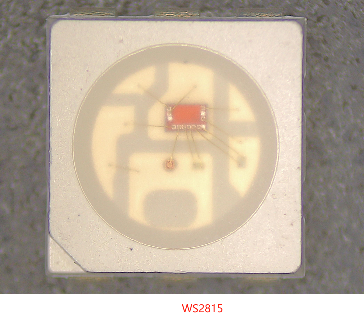
Figure 1. WS2815-labeled sample supplied by iPixel. The photograph illustrates package construction; it does not verify the exact WS2815E revision.
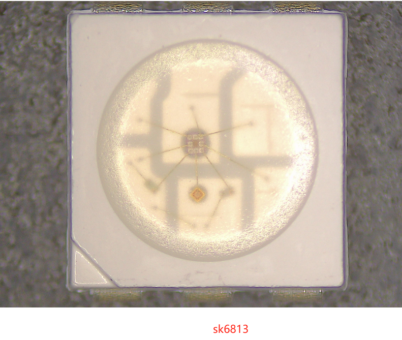
Figure 2. SK6813-labeled sample supplied by iPixel. The photograph does not independently verify the SK6813HV-09-6P-003 suffix or optical bin.
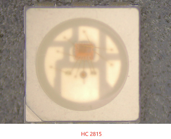
Figure 3. HC2815-labeled sample supplied by iPixel. Focus, lighting and orientation differ among the three photographs.
The images help engineers recognize that a 5050 addressable LED is an assembly of control circuitry, light-emitting dies, internal interconnections and package optics. They are not calibrated dimensional comparisons. Apparent die size, wire color and surface texture are insufficient to determine wire metallurgy, encapsulant chemistry, thermal resistance or electrical performance. Use drawings and measurements for those questions.
9. A second data input does not establish identical bypass behavior
WS2815E explicitly describes dual-signal transmission and continued overall display when a single pixel is damaged. HC identifies a BIN auxiliary input and supplies an application wiring diagram. SK identifies DIN2, but its function wording and simplified connection diagram do not fully explain the second-input behavior. [1, pp. 1–4; 2, pp. 4, 8; 3, pp. 4, 10]
Before specifying signal continuity, obtain the exact connection diagram, first-pixel input treatment, data alignment rules and supported interruption conditions. Do not infer that a second input can bypass every interruption, including a broken supply or ground. Nor should dual-input behavior be treated as interchangeable solely because the devices have six pins.
10. Selection matrix for OEM projects
| Project requirement | Starting point | Decision evidence needed |
|---|---|---|
| Preserve an existing WS2815E board | Evaluate the exact WS2815E configuration already designed in | Match approved revision, VCC capacitor arrangement, pinout and firmware; redesign the board for HC/SK substitution |
| Specify an 8kHz PWM device | Shortlist reviewed HC2815 and SK6813HV variants | Confirm required dimming behavior and camera performance in the final assembly |
| Prioritize listed directional intensity | Evaluate the reviewed HC optical configuration | Measure target-color output through the real diffuser at the intended power and temperature |
| Use an RGB-order controller profile | SK6813HV has the matching documented byte order | Verify full timing and electrical compatibility; RGB order alone is insufficient |
| Use an existing GRB-order profile | WS2815E and HC2815 use documented GRB order | Verify bit timings and pinout separately; do not assume the same driver preset fits both |
| Require operation below −25°C | HC/SK documents list −40°C minima | Confirm complete strip, controller, connectors and power system against the actual environment |
| Require defined signal-continuity behavior | Review each exact second-input implementation | Obtain the complete routing and behavior specification, then verify the assembled design |
| Need task lighting rather than pixel effects | Define the optical requirement before choosing among these RGB pixels | Decide whether the application actually requires addressable RGB or a dedicated white-light solution |
For retail displays, cabinets and equipment accents, establish whether the light provides animation, status indication or primary illumination. That distinction changes the importance of color calibration, dimming behavior, optical uniformity and individually controlled pixels.
From shortlist to an approved part
- Freeze the specification: record the full order code, document revision, current option and optical bin requirements.
- Check the hardware: compare pin mapping, orientation, land pattern, supply limits and required external components.
- Check the interface: confirm input thresholds, bit timing, reset interval, byte order and second-input wiring.
- Evaluate the light: use the intended diffuser, spacing and enclosure; compare the target colors and dimming range.
- Record measured system behavior: document input power, received waveforms, update rate and temperature under the intended operating conditions.
11. Frequently asked questions
Are WS2815, SK6813 and HC2815 interchangeable?
Not automatically. In the reviewed documents, WS2815E has a different pinout from HC2815 and SK6813HV. The latter two share listed pin positions but differ in data order and timing. Confirm the full device suffix and complete design before substitution.
Is SK6813 RGB or GRB?
The supplied SK6813HV-09-6P-003 Rev. B/0 document specifies RGB transmission order, MSB first. This statement applies to that documented variant; it should not be generalized to every SK6813-labeled product.
Does 8kHz PWM mean a higher animation frame rate?
No. PWM describes internal light modulation. Animation frame rate depends on data rate, bits per pixel, pixel count, reset interval and controller overhead. Assess both separately.
Which of these LEDs is brightest?
The reviewed HC configuration lists the highest luminous-intensity ranges in the supplied tables. Those values are not a matched comparison of total light output or complete-strip efficiency. Compare finished assemblies under the same optical and electrical conditions.
Can a 3.3V controller directly drive them?
Direct compatibility is not established by these documents. HC and SK list a 4.0V minimum input-high threshold, with an inconsistent SK test condition requiring clarification. WS uses thresholds referenced to VCC. Confirm the interface for the exact part.
Can the same controller preset be used for all three?
The three documents do not establish a common guaranteed preset. In particular, the printed WS and HC T1L windows do not overlap, and SK uses a different color-byte order. Use confirmed device-specific profiles and measured signals.
12. Conclusion
Choose the complete LED implementation, not just a familiar IC family name. For these documented parts, WS2815E requires a different PCB pin mapping; SK6813HV requires RGB data order; and HC2815 combines GRB order with higher listed intensity ranges in the supplied optical configuration. HC and SK specify 8kHz PWM, while WS specifies a 2kHz port scan. Each choice still depends on the confirmed waveform, optical target, supply arrangement and exact production variant.
Need help selecting a 12V addressable LED configuration? Send iPixel your controller model, pixel count, supply arrangement, target colors, diffuser or enclosure details and required update rate. Start with our addressable RGB LED options, or discuss your OEM lighting project.
References and source qualifications
- WS2815E, 智能外控集成LED光源, V1.0; revision record dated 2021-09-23. Supplied eight-page specification. Relevant pages: 1, product overview; 2, pins and electrical limits; 3, timing and optical parameters; 4, byte order and application circuit.
- SK6813HV-09-6P-003, Rev. B/0, dated 2024-06-13. Supplied twelve-page specification. Relevant pages: 3, overview; 4–5, mechanical/pin information and limits; 6, optical/electrical parameters; 7–8, timing and RGB data order.
- HC-5050Z1GRB-12V-I6-FS / HC2815, dated 2022-09-28. Supplied seventeen-page specification. Relevant pages: 2, overview; 4–6, pins and electrical/optical parameters; 8–9, timing and GRB data order; 10, application diagram.
These are the source editions reviewed, not a claim that they are the latest manufacturer releases. Source files can be discussed through iPixel's technical-document request process. Particular clarification points are the WS supply-range classification and T1L requirement, SK's 5V input-threshold test condition and DIN2 description, and HC's reset-unit omission and conflicting minimum symbol-period statements. No undocumented corrections or comparative laboratory results are presented here.