
For a shelf fixture manufacturer, reducing dark zones starts with a loaded shelf, not an empty display. The light position, merchandise height and cable route all affect whether a proposed installation works in use. A front-edge light may illuminate the front area while tall products still obstruct the middle and rear.
This application note focuses on installation decisions: front-edge mounting, product obstruction, magnetic fixing and side cable routing. For the separate project discussion about changing the emitting direction of a rigid bar, see our retail shelf lighting uniformity guide.
1. Locate the dark zone with merchandise in place
In the installation account supplied by iPixel, the original areas of insufficient illumination were mainly in the middle and rear of the shelf. Tall bottles made the problem more noticeable by obstructing the light.
Record whether the area needing illumination is the front-facing merchandise, the middle rows or the rear. An acceptable appearance at the front does not establish adequate coverage at the back. Check representative tall packages as well as shorter products before approving the arrangement.
2. Understand the coverage of a front-edge installation
For the described arrangement, the light is mounted beneath the shelf near its front edge. The practical illumination direction is downward, mainly covering the front portion of the merchandise area below. This position should not be described as a guarantee of uniform illumination throughout the full shelf depth.
Where the middle or rear remains too dark, review the light position and merchandise obstruction in the sample. If the agreed target includes those areas, evaluate whether a different position or an additional lighting approach is needed. These are design options to assess, not changes confirmed as implemented in this project.
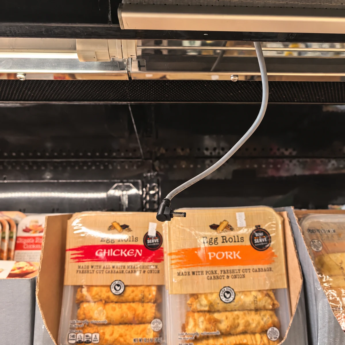
Supplied installation reference showing an under-shelf light and cable. The photograph is not a controlled demonstration of light coverage across the shelf depth.
3. Use magnetic mounting to support practical adjustment
The reported project uses magnetic fixing on the back of the light. During the on-site review, the customer can make small positional adjustments to suit the actual merchandise and fixture.
Check that the intended metal mounting surface holds the assembly securely and that the selected position remains stable during stocking and normal shelf use. Magnetic mounting provides a convenient adjustment method; it does not by itself determine optical coverage or remove shadows behind tall products.
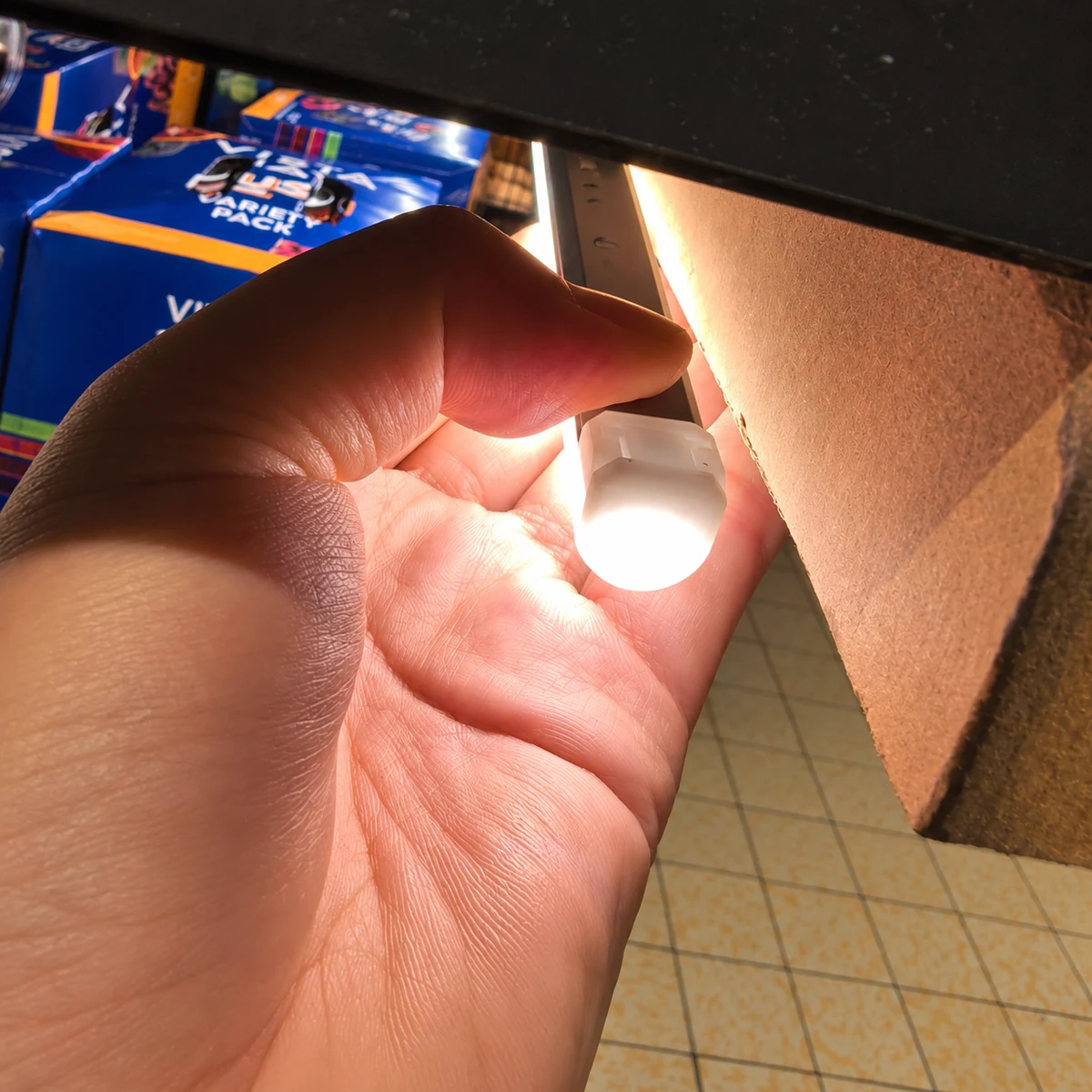
Supplied magnetic-installation reference. The image illustrates handling near the mounting surface; it does not measure magnetic holding force.
4. Plan the side cable route with the fixture
According to the supplied installation description, each shelf level has a cable routed along the side support frame. Magnetic cable clips are used to retain the cable. The available description does not establish the number of light bars per level or the complete electrical connection topology.
Review the cable path together with the mounting position so that a small adjustment does not pull on the light connection. Check access for stocking and servicing, and avoid leaving cable where it can be caught by merchandise or moving shelf parts. The supplied photographs do not document the complete side route or the magnetic cable clips.
5. Approve the layout with actual products
The customer checks the arrangement with real merchandise and makes small on-site adjustments as needed. A useful review records what was changed and which area the adjustment was intended to improve.
| Check | What to review |
|---|---|
| Front merchandise | Is the intended product-facing area adequately lit? |
| Middle and rear | Do these areas meet the project requirement, rather than an assumed full-depth target? |
| Tall bottles | Which products obstruct the light, and what remains shaded behind them? |
| Mounting | Does the adjusted magnetic position remain secure? |
| Cable route | Is the side cable retained and free from pulling or interference? |
| Final record | Are the approved position, merchandise arrangement and cable route documented? |
No measured illuminance map or before-and-after uniformity results are available for this note. It documents installation practice and review points, not a quantified claim that all dark zones were eliminated.
Prepare an installation review
Send a shelf photograph or drawing, the intended mounting position, the tallest merchandise and the location of the dark area to inquiry@ipixelleds.com. Include the side support and cable route so that the optical and installation requirements can be reviewed together.