
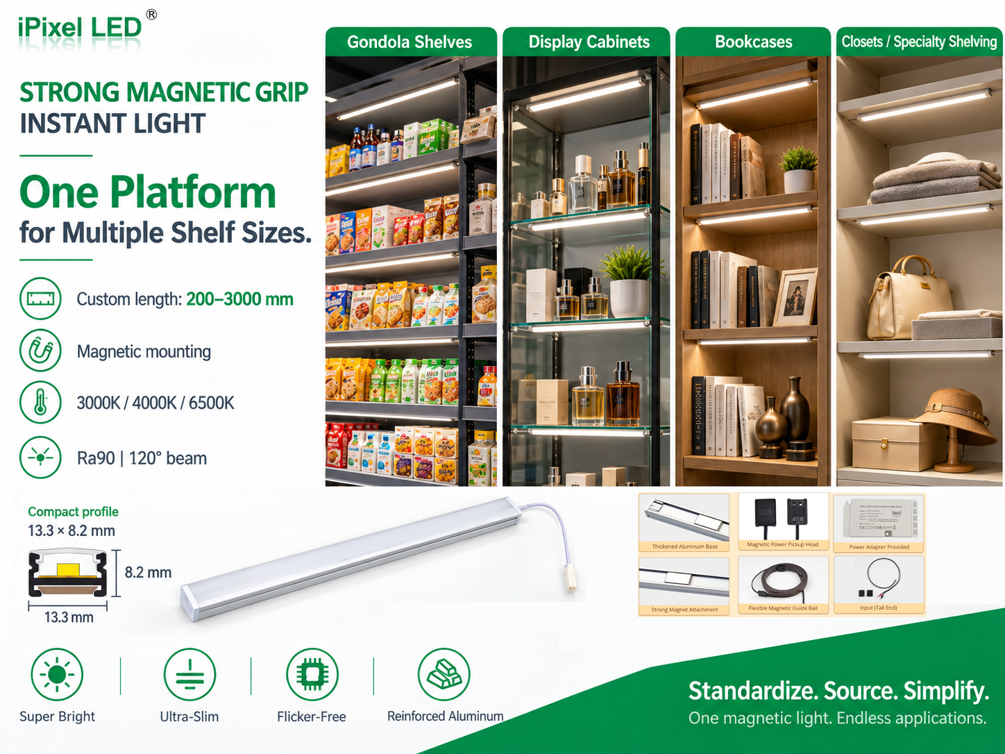
Magnetic mounting holds a light bar in position. Magnetic contact power pickup supplies it through matching electrical contacts. A shelf light can use either feature or both, so “magnetic LED bar” alone does not define how it is powered.
For fixture engineers, production teams and buyers, the useful distinction is between the mounting interface and the electrical path. This guide uses a supplied 24V shelf-lighting configuration to explain the parts to match and the information to confirm before ordering.
Two functions to specify separately
Magnetic mounting and contact power pickup
| Question | Magnetic mounting | Magnetic contact power pickup |
|---|---|---|
| What does it do? | Holds the light body on a suitable mounting surface. | Connects the light to a powered rail through conductive contacts. |
| Which parts are involved? | The light bar's rear magnetic strip and the mounting surface. | The matched rail, power tap, end-feed connection and connecting leads. |
| Does it provide electricity by itself? | No. A separately defined electrical connection is needed. | Only as part of the complete powered, correctly connected arrangement. |
| What needs checking? | Surface compatibility, coating, fit and holding performance. | Component compatibility, polarity, voltage, current limits and cable routing. |
In the example, a magnetic strip on the back of the bar attaches it beneath the shelf. Its power connection remains separate. Mounting this bar on an ordinary metal shelf does not turn that shelf into a power conductor.
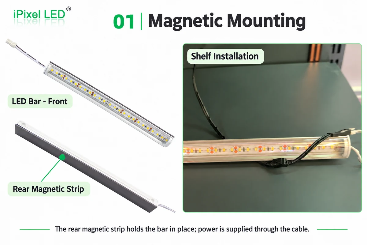
Illustration of magnetic mounting: the rear magnetic strip holds the light bar, while a cable supplies power. Select the illustration to view the full-size image.
Follow the electrical path through the matched components
The example's power path is:
DC supply → rail end-feed connection → two copper conductors → power-tap contacts → tap lead → light-side connector → light-bar PCB
The tap's magnetic structure positions and retains the contact interface. Electricity crosses the metal contact surfaces and continues through the lead to the bar. This arrangement is contact-based power delivery; it is not wireless inductive charging.
The flexible rail also uses magnetic mounting. That is a third mounting interface to consider: the light attaches to the shelf, the rail attaches to a suitable support, and the tap attaches to the rail. Each has its own fit and positioning requirements.
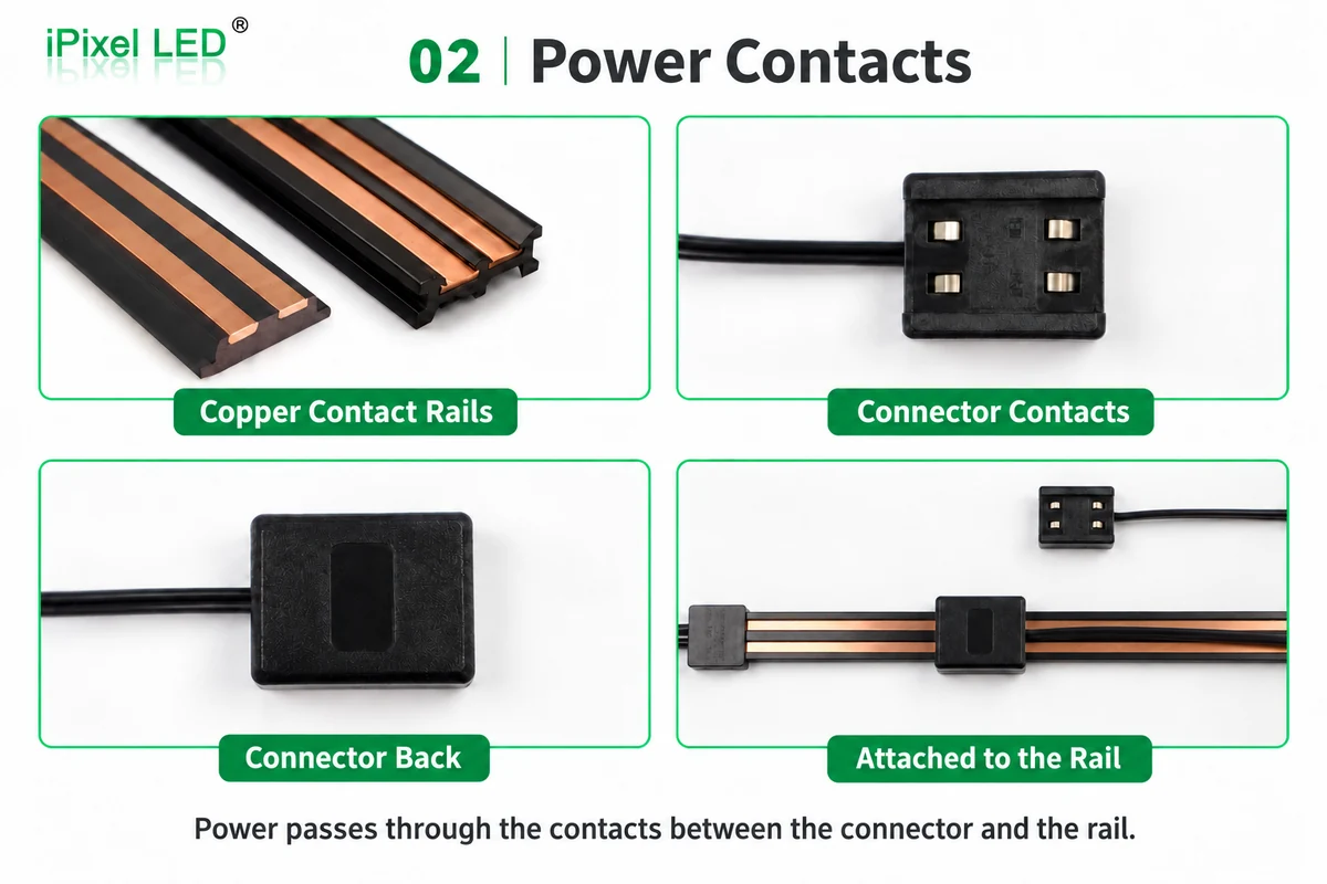
Illustration of contact power pickup. The matching connector contacts touch the rail conductors; its lead carries power onward to the light. Select the illustration to view the full-size image.
The supplied tap lead and light-side connector have been confirmed as directly mating. That confirmation applies to the selected pair. It should not be extended to every connector with the same pin count or to taps intended for another rail profile.
What the example arrangement contains
The following values describe the supplied configuration. They provide a starting point for a cabinet or fixture drawing review; they do not define a universal magnetic lighting kit.
Component information for the 24V example
| Component | Supplied information | Purpose |
|---|---|---|
| Magnet-mounted rigid LED bar | 24V; 10W/m; 1200 × 16 × 16mm; rear magnetic strip; 100mm light-side lead | Illuminates beneath the shelf and provides its own mounting interface. |
| Flexible magnetic power rail | Magnetic rubber with copper conductors; 16.5mm wide × 3.5mm thick; 1800mm project length | Provides the matched conductive path for the taps. |
| Magnetic power-tap connector | 500mm lead; 20AWG; selected lead connects directly to the light-side connector | Transfers power from the rail to the bar through the lead. |
| Supply and end feed | 24V DC; 150W rated supply; matched rail end-feed connection | Feeds the rail. Final feed parts and wiring follow the approved configuration. Illustrative component overview. The supply, rail, tap and light must be selected as a compatible arrangement. Select the illustration to view the full-size image. |
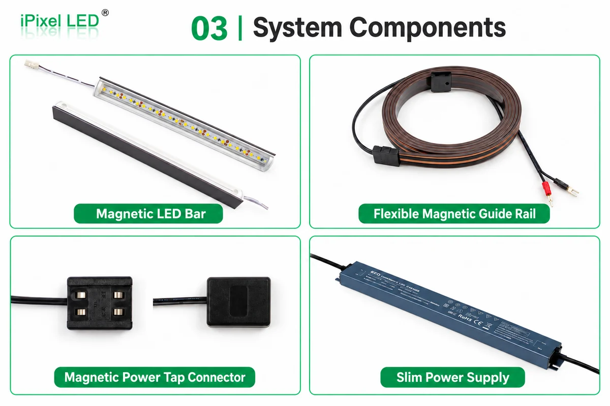
Keep the rail type, tap and end-feed connection together in the component list. Flexible and rigid rail systems should not be assumed to accept the same tap. A rear mounting magnet also does not identify which power connector belongs to a light.
Keep each current rating attached to its component
At the stated 10W/m, a 1.2m bar has a calculated nominal load of approximately 12W. At 24V, its nominal current is approximately 0.5A:
1.2m × 10W/m ≈ 12W
12W ÷ 24V ≈ 0.5A per bar
These are calculations from the supplied length and power-per-metre value, not measurements of a complete installation. The supply's 150W rating is its rated capacity, not the consumption of a shelf or light bar.
The supplied rail information gives DC12–36V and a maximum current figure of 12A. That figure belongs to the rail. Ratings for the selected tap, end-feed connection and other series connections have not been supplied, so it cannot be used to declare a 12A capacity for the complete arrangement.
Likewise, dividing the supply wattage by one bar's calculated load does not establish an approved maximum light count. Review the proposed total load alongside every shared feed path, tap, connector and cable limit, then confirm operation in the intended layout. The available information does not establish a maximum number of bars for this example.
What can move when the shelf position changes?
The bar can be detached from its mounting surface and repositioned. The tap can be detached and reattached at a compatible contact position along the matched rail. The rail itself can be repositioned where the mounting surface and end-feed lead permit.
Those are different adjustments. A 1800mm rail does not automatically provide 1800mm of usable shelf travel. The effective contact area, end connections, shelf structure, the tap's 500mm lead and the light's 100mm lead all affect where the parts can be placed. Their lengths should not simply be added to declare a guaranteed adjustment range.
No instruction permitting adjustment while energized has been provided for this configuration. The assembly sequence used in this guide therefore starts with power disconnected: confirm the matched parts, position the rail and light, attach the tap, connect the lead, organize the cable and inspect the connections before powering the lights.
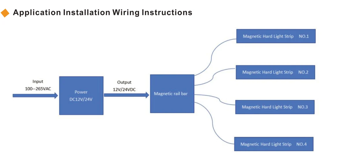
Generic system relationship illustration showing 12V/24V options. The example discussed in this guide uses 24V. Four lights are illustrative, not a maximum connection count; this is not a complete terminal wiring drawing. Select the illustration to view the full-size image.
Check the shelf surface and the complete connection
A magnet-compatible surface is needed for each magnetic mounting interface. “Metal shelving” is too broad a description for approval. Surface material, coating thickness, flatness and any gap between the magnet and support need to be considered with the actual fixture.
Provide space for the bar, rail, tap, supply, connector bodies and cable bends. Route the tap lead so a change of shelf position does not pull on the connection or obstruct fixture assembly. The rail conductors must meet their matching contacts; an ordinary mounting panel cannot replace the specified rail.
For a new configuration, a representative fixture check should cover:
- Holding performance of the bar and rail on the actual mounting surfaces.
- Correct contact seating, connector mating and polarity.
- Connection and cable routing at the proposed shelf positions.
- Power delivery under the proposed connected load.
- Repeat positioning and reconnection according to the selected components' instructions.
The earlier project feedback described secure mounting and convenient connection on the customer's shelving. It does not provide a documented retention force, reconnection-cycle count or electrical endurance result. The checks above are selection and validation items for a new configuration.
What to send for a component-matching review
Send the fixture drawing, shelf material and coating information, light positions, intended adjustment range, rail length, supply location and cable routes. State the bar voltage, length and quantity at each shelf. Include rail and tap identification, mating connector details, polarity information and available component ratings.
Keep a drawing of the full connection path with the approved parts list. This lets purchasing identify the intended rail/tap pair and helps assembly teams distinguish a mounting change from a change to the power connection.
Frequently Asked Questions
Will a magnet-mounted LED bar light up on an ordinary metal shelf?
Mounting alone does not supply power. The bar needs its specified electrical connection, whether that is ordinary wired power or a matched contact-rail arrangement.
Is magnetic power pickup completely wireless?
In this example it uses conductive contacts and a lead from the tap to the bar. It should be specified as contact power pickup rather than wireless induction.
Can any magnetic tap be used on the rail?
No. Confirm the rail profile, contact geometry, polarity, voltage and component current limits. Physical magnetic attraction does not establish electrical compatibility.
Does the rail's 12A figure define the complete system capacity?
No. Other connection and feed components have their own limits. Their ratings are needed before approving a total load or maximum light count.
Can the tap be moved while the lights are powered?
This configuration has no supplied instruction permitting energized adjustment. Disconnect power before repositioning or reconnecting, and follow the selected components' installation instructions.
Related engineering and products
- Retail Shelf & Display Lighting Solutions
- Custom LED Strip Engineering
- LED Light Bars
- Cable Connectors
- Power Supplies
Review Your Shelf Lighting Connection
Send the fixture layout and proposed component list to inquiry@ipixelleds.com. iPixel can review the mounting interfaces, matched rail and tap, light-bar leads and supply arrangement against your shelf design.